A/T Shaft Assembly and Housing Installation


Exploded View
NOTE: Refer to the Exploded View as needed during the following procedure.
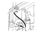
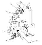
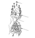
  1. Install the differential assembly in the torque converter housing.
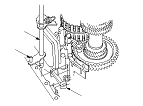
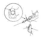
  1. Install the baffle plate on the servo body.
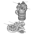
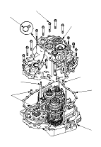
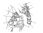
  1. Assemble the mainshaft, the countershaft, and the secondary shaft.
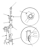
  1. Join the mainshaft subassembly (A), the countershaft subassembly (B), and the secondary shaft subassembly (C) together. Then install them in the torque converter housing. Do not bump the countershaft on the baffle plate (D).
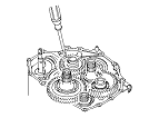
  1. Make sure if the countershaft subassembly and the differential assembly (E) are clear of the baffle plate.

  1. If the detent arm was removed, install the detent arm (A) with the arm collar (B) on the servo body (C), and install a new lock washer (D) by aligning its cutout (E) with the projection (F) of the servo body. Install and tighten the bolt, then bend the lock tab of the lock washer against the bolt head.

  1. Install the selector control shaft (A) in the torque converter housing aligning the manual valve lever pin (B) on the selector control shaft with the guide of the manual valve (C). Pull the manual valve gently when aligning the manual valve with the selector control shaft.

  1. Hook the detent spring (A) to the detent arm (B).

  1. Turn the shift fork shaft (A) so the large chamfered hole (B) is facing the fork bolt hole (C) of the reverse shift fork (D).
  1. Install the shift fork and the reverse selector together on the shift fork shaft and the countershaft subassembly. Secure the shift fork to the shift fork shaft with the lock bolt and a new lock washer (E), then bend the lock tab of the lock washer against the bolt head.
  1. Install the needle bearing and the countershaft reverse gear on the countershaft subassembly.

  1. Install the three dowel pins (A) and a new gasket (B) on the torque converter housing (C).
  1. Align the spring pin of the selector control shaft (D) with the transmission housing groove (E) by turning the selector control shaft on the torque converter side.
    NOTE: Do not squeeze the end of the selector control shaft tips together when turning the selector control shaft. If the selector control shaft tips are squeezed together, it will cause a faulty shift position signal or position due to the play between the selector control shaft and the transmission range switch.
  1. Place the transmission housing (F) on the torque converter housing. Do not install the input shaft (mainshaft) speed sensor and the output shaft (countershaft) speed sensor before installing the transmission housing on the torque converter housing.

  1. Wrap a screwdriver tip with tape to prevent damage to the reverse idler gear teeth. Engage the reverse idler gear with reverse gears by rotating the reverse idler gear using the screwdriver.
  1. Install the transmission housing mounting bolts, and tighten the 19 bolts to 44 N·m (4.5 kgf·m, 33 lbf·ft) in at least two steps, in a crisscross pattern.

  1. Install a new O-ring (A) on the input shaft (mainshaft) speed sensor (B), then install the input shaft (mainshaft) speed sensor in the transmission housing.
  1. Install a new O-ring (C) on the output shaft (countershaft) speed sensor (D), then install the output shaft (countershaft) speed sensor with the speed sensor washer (E) (only for K24Z3 engine model).
    NOTE: The speed sensor washer is equipped on K24Z3 engine model; R20A3 engine model do not have a speed sensor washer.

  1. Install a new O-ring (F) on the shift solenoid wire harness (G), then install the shift solenoid wire harness in the transmission housing. Secure the shift solenoid wire harness with the bolt (H).
  1. Connect the shift solenoid wire harness terminals to the shift solenoid valves:
    • BLU wire connector to shift solenoid valve A.
    • ORN wire connector to shift solenoid valve B.
    • GRN wire connector to shift solenoid valve C.
    • YEL, WHT, and WHT wire connector to shift solenoid valve D.
    • RED wire connector to shift solenoid valve E.

  1. Install a new gasket (A), the dowel pins (B), and the shift solenoid valve cover (C), and secure the cover with the bolts.