-
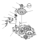
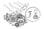
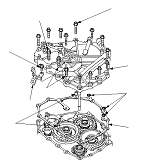
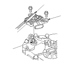
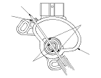
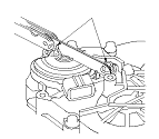
Install the park lever (A) and the park lever stop (B) on the selector control shaft (C), then install the lock bolt with a new lock washer (D). Do not bend the lock tab of the lock washer until
Step 18
.
-
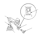
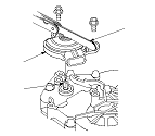
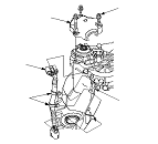
Install the park pawl shaft (E), the park pawl spring (F), the park pawl (G), and the stop shaft (H) on the transmission housing.
-
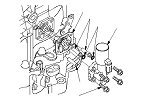
Lubricate the following parts with ATF:
-
Threads and splines of the countershaft.
-
The old conical spring washer and the old locknut.
-
Areas where the park gear contacts the conical spring washer.
-
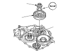
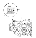
Install the park gear (I), the old conical spring washer (J), and the old locknut (K) on the countershaft.
-
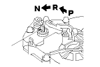
Lift the park pawl up, and engage it with the park gear, then tighten the locknut to 226 N·m (23.0 kgf·m, 166 lbf·ft).
NOTE:
-
Do not tap the park gear to install.
-
Use a torque wrench to tighten the locknut. Do not use an impact wrench.
-
Countershaft locknut has left-hand threads.
-
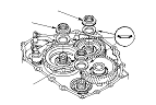
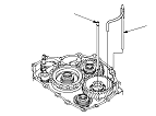
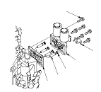
Remove the locknuts and the conical spring washers from the mainshaft and the countershaft.
-
Lubricate the threads of the shafts, new locknuts, and new conical spring washers with ATF.
|
|