M/T Countershaft Reassembly
|
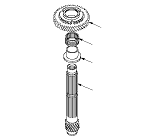
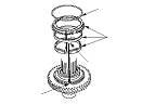
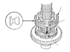
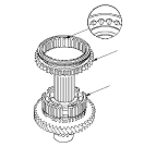
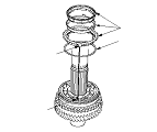
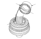
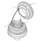
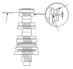
Exploded View
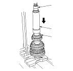
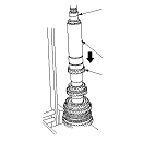
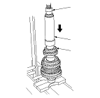
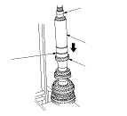
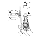
Special Tools Required
Inner driver handle, 40 mm
07746-0030100
Inner bearing driver attachment, 30 mm
07746-0030300
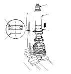
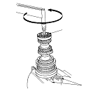
NOTE: Refer to the Exploded View, as needed, during this procedure.
|
|
|
|
|
|
|
|
|
|
|
|
|
|
|
|
|
|
|
|
|
|
|
|
|
|
|
|