M/T Assembly Reassembly

NOTE:
  • Prior to reassembly, clean all parts in solvent, dry them, and apply MTF to any contact surfaces.
  • The illustrations show K24Z3 engine model.
  1. Install the magnet (A) and differential assembly (B).

  1. Install the 28 mm spring washer (A) and the 28 mm washer (B) over the ball bearing (C). Note the installation direction of the spring washer.
  1. Apply vinyl tape to the mainshaft splines (D) to protect the seal. Install the mainshaft assembly (E) and the countershaft assembly (F) with the shift fork assembly (G), as an assembly.

  1. Install the reverse shift fork (A).

  1. Install the reverse idler gear (A) and reverse idler gear shaft (B) by aligning the mark (C) on the clutch housing with the reverse idler gear shaft hole (D).

  1. Install the baffle plate (A).

  1. Select the proper size 72 mm shim (A) according to the measurements made during the Mainshaft Thrust Clearance Adjustment. Install the oil gutter plate (B), oil guide plate M, and 72 mm shim into the transmission housing (C).
  1. Clean any dirt or oil from the transmission housing sealing surface.

  1. Apply liquid gasket (P/N 08C70-K0234M, 08C70-K0334M, or 08C70-X0331S) evenly to the clutch housing mating surface of the transmission housing.
    NOTE: Do not install components if too much time has passed after applying the liquid gasket. Instead, remove the old residue and reapply the liquid gasket.

  1. Install three 14 x 20 mm dowel pins (A).
  1. Place the transmission housing on the clutch housing, being careful to line up the shafts.
  1. While expanding the 72 mm snap ring (B) on the countershaft ball bearing using the snap ring pliers, push the transmission housing down to start the countershaft ball bearing through the snap ring.
    Then release the pliers, and push down the housing until it bottoms and the snap ring snaps in place in the countershaft ball bearing snap ring groove.
    NOTE: Install the 32 mm sealing cap (C) after setting in the 72 mm snap ring.

  1. Make sure the 72 mm snap ring (A) is securely seated in the groove of the countershaft bearing.
    Dimension (1) as installed:
    3.3−6.0 mm (0.13−0.24 in.)

  1. Apply liquid gasket (P/N 08C70-K0234M, 08C70-K0334M, or 08C70-X0331S) to the threads of the 32 mm sealing cap, and install it on the transmission housing.

  1. Install by finger-tight the 8 mm flange bolts with the transmission hanger A, the transmission hanger B, and the harness bracket (K24Z3 engine model) (C).

  1. Tighten the 8 mm flange bolts in a crisscross pattern in several steps.
    Specified Torque:
    8 x 1.25 mm
    27 N·m (2.8 kgf·m, 20 lbf·ft)

  1. Clean any dirt or oil from the change lever assembly sealing surface.

  1. Apply liquid gasket (P/N 08C70-K0234M, 08C70-K0334M, or 08C70-X0331S) evenly to the transmission housing mating surface of the change lever assembly.
    NOTE: Do not install components if too much time has passed after applying the liquid gasket. Instead, remove the old residue and reapply the liquid gasket.

  1. Install the 8 x 14 mm dowel pins (A) and the change lever assembly (B).
  1. Apply liquid gasket (P/N 08C70-K0234M, 08C70-K0334M, or 08C70-X0331S) to the threads of the interlock bolt (C), and install it on the transmission housing.

  1. Install the filler plug (A) with a new washer finger-tight, and install the drain plug (B) and 10 mm flange bolt (C) with new sealing washers (D).
  1. Install the new O-ring (E), plain washer (F), and output shaft (countershaft) speed sensor (G).

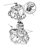
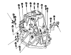
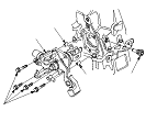
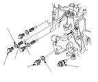
  1. Install the steel balls (A), the springs (B), the dent bolts (C) with a new washers (D).
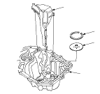
  1. Install the 20 mm bolt (E) with the new 20 mm sealing washer (F).
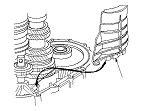
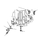
  1. Apply liquid gasket (P/N 08C70-K0234M, 08C70-K0334M, or 08C70-X0331S) to the threads of the back-up light switch (G), and install it in the transmission housing.