Clutch Replacement

Special Tools Required

Slide hammer weight
 07741-0010201

Bearing remover shaft
 07936-3710600

Driver handle, 15 x 135L
 07749-0010000

Bearing driver attachment, 22 x 24 mm
 07746-0010800

Ring gear holder
 07LAB-PV00100

Shaft (clutch alignment tool),
 07PAF-0020100

Taper cone (clutch alignment tool),
 07PAF-0020200

Clutch alignment pilot, 21 mm
 07PAF-0020370

Remover handle
 07936-3710100
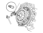
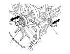
NOTE: The illustrations show K24Z3 engine model.
Engine Side
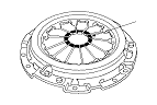
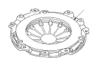
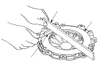
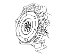
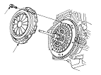
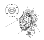
Pressure Plate Inspection and Removal
  1. Check the height evenness of the diaphragm spring fingers using the dial indicator (A). If the most measurement difference is more than the service limit, replace the pressure plate.
    Standard (New):
    0.6 mm (0.02 in.) max.
    Service Limit:
    0.8 mm (0.03 in.)


  1. Install the ring gear holder (A), the shaft (clutch alignment tool) (B), the taper cone (clutch alignment tool) (C), and the 21 mm clutch alignment pilot (D).
  1. To prevent warping, unscrew the pressure plate mounting bolts (E) in a crisscross pattern in several steps, then remove the pressure plate (F).

  1. Inspect the fingers of the diaphragm spring (A) for wear at the release bearing contact area.

  1. Inspect the pressure plate surface (A) for wear, cracks, and burning.

  1. Inspect for warpage using a straight edge (A) and a feeler gauge (B). Measure across the pressure plate (C). If the most measurement difference is more than the service limit, replace the pressure plate.
    Standard (New):
    0.08 mm (0.003 in.) max.
    Service Limit:
    0.15 mm (0.006 in.)


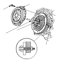
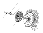
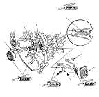
Clutch Disc Inspection and Removal
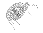
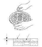
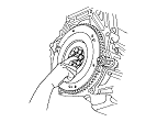
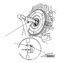
  1. Remove the clutch disc (A), the shaft (clutch alignment tool) (B), the taper cone (clutch alignment tool) (C), and the 21mm clutch alignment pilot (D).
  1. Inspect the lining of the clutch disc for signs of slippage or oil. If the clutch disc looks burnt or is oil soaked, replace the clutch disc. If the clutch disc is oil soaked, find and repair the source of the oil leak.

  1. Measure the clutch disc thickness. If the measurement is less than the service limit, replace the clutch disc.
    R20A3 engine model:
    Standard (New):
    8.25−8.95 mm (0.325−0.352 in.)
    Service Limit:
    6.0 mm (0.24 in.)
    K24Z3 engine model:
    Standard (New):
    7.30−7.90 mm (0.287−0.311 in.)
    Service Limit:
    6.0 mm (0.24 in.)


  1. Measure the rivet depths from the clutch disc lining surface (A) to the rivets (B) on both sides. If the measurement is less than the service limit, replace the clutch disc.
    R20A3 engine model:
    Standard (New):
    1.20−1.70 mm (0.047−0.067 in.)
    Service Limit:
    0.7 mm (0.03 in.)
    K24Z3 engine model:
    Standard (New):
    1.15−1.75 mm (0.045−0.069 in.)
    Service Limit:
    0.7 mm (0.03 in.)


Flywheel Inspection
  1. Remove the ring gear holder.
  1. Inspect the ring gear teeth for wear and damage.
  1. Inspect the clutch disc mating surface on the flywheel for wear, cracks, and burning.
  1. Measure the flywheel (A) runout using a dial indicator (B). Through at least two full turns with pushing against the flywheel each time you turn it to take up the crankshaft thrust washer clearance. If the measurement is not within the standard, replace the flywheel, and recheck the runout; go to Step 16 .
    Standard (New):
    0.05 mm (0.002 in.) max.
    Service Limit:
    0.15 mm (0.006 in.)


Flywheel Replacement
  1. Install the ring gear holder (A).
  1. Loosen the flywheel mounting bolts in a crisscross pattern in several steps. Remove the bolts, then remove the flywheel and the ring gear holder.
  1. Install the flywheel on the crankshaft, and install the mounting bolts finger-tight.

  1. Install the ring gear holder (A), then torque the flywheel mounting bolts (B) in a crisscross pattern in several steps.

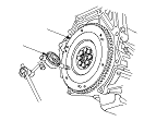
Crankshaft Pilot Bushing Inspection
  1. Inspect the crankshaft pilot bushing for wear and damage.
  1. Inspect the inside surface of the crankshaft pilot bushing with your finger. If the crankshaft pilot bushing is not smooth, replace it; go to Step 22 .

Crankshaft Pilot Bushing Replacement
  1. Remove the crankshaft pilot bushing (A) using slide hammer weight (B), remover handle (C), and bearing remover shaft (D).

  1. Install the new crankshaft pilot bushing (A) into the crankshaft using the 15 x 135L driver handle (B) and 22 x 24 mm bearing driver attachment (C). Apply a light coat of molybdenum grease to the crankshaft pilot bushing surface.

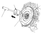
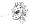
Clutch Disc and Pressure Plate Installation
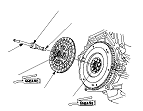
  1. Temporarily install the clutch disc onto the splines of the transmission mainshaft. Make sure the clutch disc slides freely on the mainshaft.
  1. Apply a light coat of molybdenum grease to the crankshaft pilot bushing (A).
  1. Apply molybdenum grease to the splines (B) of the clutch disc (C), then install the clutch disc using the shaft (clutch alignment tool) (D), the taper cone (clutch alignment tool) (E), and the 21 mm clutch alignment pilot (F).

  1. Install the pressure plate (A) and the mounting bolts (B) finger-tight.

  1. Torque the mounting bolts (A) in a crisscross pattern. Tighten the bolts in several steps to prevent warping the diaphragm spring.
    Specified Torque:
    25 N·m (2.6 kgf·m, 19 lbf·ft)

  1. Remove the ring gear holder (B) and the shaft (clutch alignment tool) (C), the taper cone (clutch alignment tool) (D), and the 21 mm clutch alignment pilot.
  1. Make sure the diaphragm spring fingers are all the same height.
  1. Do the release bearing inspection, and replace if it necessary.

Transmission Side
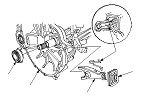
Release Bearing Removal
  1. Remove the release fork boot (A) from the clutch housing (B).
  1. Remove the release fork (C) from the clutch housing by squeezing the release fork set spring (D) with pliers. Remove the release bearing (E).

Release Bearing Inspection
  1. Check the play of the release bearing by spinning it by hand. If there is excessive play or noise, replace the release bearing.
    NOTE: The release bearing is packed with grease. Do not wash it in solvent.

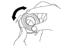
Release Bearing Installation
  1. Apply molybdenum grease to the release fork (A), release fork bolt (B), the release bearing (C), and the release bearing guide (D) in the shaded areas, then set the release fork set spring (E).
    NOTE: Replace the release fork bolt if necessary.
  1. With the release fork slid between the release bearing pawls, install the release bearing on the mainshaft while inserting the release fork through the hole in the clutch housing.
  1. Align the detent of the release fork with the release fork bolt, then press the release fork over the release fork bolt squarely.
  1. Install the release fork boot (F). Make sure the boot seals around the release fork and clutch housing.

  1. Move the release fork (A) right and left to make sure that it fits properly against the release bearing (B) and that the release bearing slides smoothly. Wipe off any excess grease.