Disconnect under-hood fuse/relay box connector D (10P).
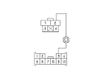
Disconnect the brake pedal position switch 4P connector.
Check for continuity between the brake pedal position switch 4P connector terminal No. 2 and the under-hood fuse/relay box connector D (10P) terminal No. 3.
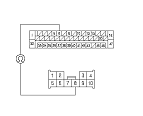
Check for continuity between the VSA modulator-control unit 47P connector terminal No. 6 and the under-hood fuse/relay box connector D (10P) terminal No. 8.
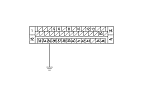
Check for continuity between the VSA modulator-control unit 47P connector terminal No. 35 and the under-hood fuse/relay box connector D (10P) terminal No. 7.
Repair open in the wire between the VSA modulator-control unit and the under-hood fuse/relay box.■
Turn the ignition switch to ON (II).
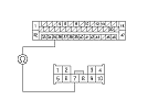
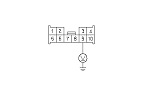
Measure the voltage between under-hood fuse/relay box connector D (10P) terminal No. 9 and body ground.
Is there battery voltage?
YES
-
Replace the relay circuit board.■
NO
-
Repair open in the wire between the No. 6 (7.5 A) fuse in the driver's under-dash fuse/relay box and the under-hood fuse/relay box.■
Turn the ignition switch to LOCK (0).
Check for continuity between the VSA modulator-control unit 47P connector terminal No. 6 and the under-hood fuse/relay box connector D (10P) terminal No. 8.
Turn the ignition switch to LOCK (0), then turn it to ON (II) again.
After the VSA indicator goes off, press the brake pedal for 3 seconds or more.
Check for DTCs with the HDS.
Is DTC 69 indicated?
YES
-
Check for loose terminals in the VSA modulator-control unit 47P connector. If the VSA modulator-control unit was updated,
substitute a known-good VSA modulator-control unit,
then retest. If the VSA modulator-control unit was substituted, go to
Step 1
.
NO
-
If the VSA modulator-control unit was updated, troubleshooting is complete. If the VSA modulator-control unit was substituted,
replace the original VSA modulator-control unit.
If any other DTCs are indicated, go to the indicated DTCs troubleshooting.■