DTC Troubleshooting: 25, 26, 104

DTC 25:
 Yaw Rate Sensor
DTC 26:
 Lateral Acceleration Sensor
DTC 104:
 Yaw Rate-Lateral Acceleration Sensor
  1. Check the size, air pressure, and the amount of wear of all four tyres, and check the wheel alignment.
Is the tyre condition and wheel alignment OK?
YES -
Go to Step 2 .
NO -
Make sure the suspension is not modified, and adjust the wheel alignment correctly, and recheck by test-driving.■
  1. Check the YAW/G COMBINE SENSOR DIAGNOSIS in the VSA FREEZE DATA with the HDS.
Is YAW/G COMBINE SENSOR DIAGNOSIS NORMAL?
YES -
Go to Step 3 .
NO -
  1. Turn the ignition switch to LOCK (0).
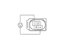
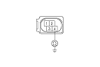
  1. Disconnect the yaw rate-lateral acceleration sensor 4P connector.
  1. Turn the ignition switch to ON (II).
  1. Measure the voltage between yaw rate-lateral acceleration sensor 4P connector terminals No. 1 and No. 4.
Is there battery voltage?
YES -
Go to Step 11 .
NO -
Go to Step 7 .
  1. Turn the ignition switch to LOCK (0).
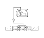
  1. Disconnect the driver's under-dash fuse/relay box connector P (20P).

  1. Check for continuity between yaw rate-lateral acceleration sensor 4P connector terminal No. 1 and driver's under-dash fuse/relay box connector P (20P) terminal No. 7.
Is there continuity?
YES -
Go to Step 10 .
NO -
Repair open in the wire between the yaw rate-lateral acceleration sensor and the driver's under-dash fuse/relay box.■

  1. Check for continuity between yaw rate-lateral acceleration sensor 4P connector terminal No. 4 and body ground.
Is there continuity?
YES -
Go to Step 11 .
NO -
Repair open in the wire between the yaw rate-lateral acceleration sensor and body ground (G503).■

  1. Check for continuity between VSA modulator-control unit 47P connector terminals No. 12, No. 13 and yaw rate-lateral acceleration sensor 4P connector terminals No. 3, No. 2 individually.
Is there continuity?
YES -
Go to Step 13 .
NO -
Repair open in the wire between the VSA modulator-control unit and the yaw rate-lateral acceleration sensor.■
  1. Reconnect all connectors.
  1. Turn the ignition switch to ON (II).
  1. Clear the DTC with the HDS.
  1. Test-drive the vehicle around a number of corners.
    NOTE: Drive the vehicle on a straight section of road, not on a lift.
  1. Check for DTCs with the HDS.
Is DTC 25, 26, or 104 indicated?
YES -
Go to Step 20 .
NO -
  1. Test-drive the vehicle around a number of corners.
    NOTE: Drive the vehicle on a straight section of road, not on a lift.
  1. Check for DTCs with the HDS.
Is DTC 25, 26, or 104 indicated?
YES -
Check for loose terminals in the VSA modulator-control unit 47P connector. If the VSA modulator-control unit was updated, substitute a known-good VSA modulator-control unit, then retest. If the VSA modulator-control unit was substituted, go to Step 1 .
NO -
If the VSA modulator-control unit was updated, troubleshooting is complete. If the VSA modulator-control unit was substituted, replace the original VSA modulator-control unit. If any other DTCs are indicated, go to the indicated DTCs troubleshooting.■