DTC Troubleshooting: 11, 13, 15, 17

DTC 11, 13, 15, 17:
 Wheel Speed Sensor (Short to Power/Short to Body Ground/Open)
  1. Turn the ignition switch to LOCK (0).
  1. Start the engine.
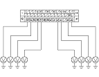
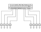
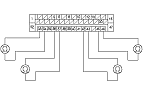
  1. Measure the voltage between body ground and the appropriate wheel speed sensor +B and GND terminals of the VSA modulator-control unit 47P connector individually (see table).
    DTC
    Appropriate Terminal
    +B
    GND
    11 (Right-front)
    FR +B:
    No. 34
    FR-GND:
    No. 33
    13 (Left-front)
    FL +B:
    No. 45
    FL-GND:
    No. 46
    15 (Right-rear)
    RR +B:
    No. 43
    RR-GND:
    No. 42
    17 (Left-rear)
    RL +B:
    No. 36
    RL-GND:
    No. 37

Is there 0.1 V or more?
YES -
Repair short to power in the wire between the VSA modulator-control unit and the appropriate wheel speed sensor.■
NO -
Go to Step 5 .
  1. Turn the ignition switch to LOCK (0).

  1. Check for continuity between body ground and the appropriate wheel speed sensor +B and GND terminals of the VSA modulator-control unit 47P connector individually (see table).
    DTC
    Appropriate Terminal
    +B
    GND
    11 (Right-front)
    FR +B:
    No. 34
    FR-GND:
    No. 33
    13 (Left-front)
    FL +B:
    No. 45
    FL-GND:
    No. 46
    15 (Right-rear)
    RR +B:
    No. 43
    RR-GND:
    No. 42
    17 (Left-rear)
    RL +B:
    No. 36
    RL-GND:
    No. 37

Is there continuity?
YES -
Go to Step 7 .
NO -
Go to Step 9 .
  1. Disconnect the appropriate wheel speed sensor 2P connector.

  1. Check for continuity between body ground and the appropriate wheel speed sensor +B and GND terminals of the VSA modulator-control unit 47P connector individually (see table).
    DTC
    Appropriate Terminal
    +B
    GND
    11 (Right-front)
    FR +B:
    No. 34
    FR-GND:
    No. 33
    13 (Left-front)
    FL +B:
    No. 45
    FL-GND:
    No. 46
    15 (Right-rear)
    RR +B:
    No. 43
    RR-GND:
    No. 42
    17 (Left-rear)
    RL +B:
    No. 36
    RL-GND:
    No. 37

Is there continuity?
YES -
Repair short to body ground in the wire between the VSA modulator-control unit and the wheel speed sensor.■
NO -
  1. Disconnect the appropriate wheel speed sensor 2P connector.

  1. Check for continuity between the appropriate wheel speed sensor +B and GND terminals of the VSA modulator-control unit 47P connector (see table).
    DTC
    Appropriate Terminal
    +B
    GND
    11 (Right-front)
    FR +B:
    No. 34
    FR-GND:
    No. 33
    13 (Left-front)
    FL +B:
    No. 45
    FL-GND:
    No. 46
    15 (Right-rear)
    RR +B:
    No. 43
    RR-GND:
    No. 42
    17 (Left-rear)
    RL +B:
    No. 36
    RL-GND:
    No. 37

Is there continuity?
YES -
Repair short in the wires between the VSA modulator-control unit and the wheel speed sensor.■
NO -
Go to Step 11 .

  1. Connect wheel speed sensor 2P connector terminals No. 1 and No. 2 to body ground with a jumper wire.
    DTC
    Appropriate Wheel Speed Sensor
    11
    Right-front
    13
    Left-front
    15
    Right-rear
    17
    Left-rear


  1. Check for continuity between body ground and the appropriate wheel speed sensor +B and GND terminals of the VSA modulator-control unit 47P connector individually (see table).
    DTC
    Appropriate Terminal
    +B
    GND
    11 (Right-front)
    FR +B:
    No. 34
    FR-GND:
    No. 33
    13 (Left-front)
    FL +B:
    No. 45
    FL-GND:
    No. 46
    15 (Right-rear)
    RR +B:
    No. 43
    RR-GND:
    No. 42
    17 (Left-rear)
    RL +B:
    No. 36
    RL-GND:
    No. 37

Is there continuity?
YES -
Go to Step 13 .
NO -
Repair open in the wire between the VSA modulator-control unit and the wheel speed sensor.■
  1. Reconnect all connectors.
  1. Turn the ignition switch to ON (II).
  1. Clear the DTC with the HDS.
  1. Test-drive the vehicle. Drive the vehicle at 30 km/h (19 mph) or more.
    NOTE: Drive the vehicle on a straight section of road, not on a lift.
  1. Check for DTCs with the HDS.
Is DTC 11, 13, 15, and/or 17 indicated?
YES -
Go to Step 19 .
NO -
  1. Test-drive the vehicle. Drive the vehicle at 30 km/h (19 mph) or more.
    NOTE: Drive the vehicle on a straight section of road, not on a lift.
  1. Check for DTCs with the HDS.
Is DTC 11, 13, 15, and/or 17 indicated?
YES -
Check for loose terminals in the VSA modulator-control unit 47P connector. If the VSA modulator-control unit was updated, substitute a known-good VSA modulator-control unit, then retest. If the VSA modulator-control unit was substituted, go to Step 1 .
NO -
If the VSA modulator-control unit was updated, troubleshooting is complete. If the VSA modulator-control unit was substituted, replace the original VSA modulator-control unit. If any other DTCs are indicated, go to the indicated DTCs troubleshooting.■