|
DTC B1825:
Power Seat Slide Motor Pulse Error
DTC B1825 is stored when the slide switch is operated more than 1 second after the seat moves to the most backward position, even when the system is OK.
-
Clear the DTCs with the HDS.
-
Turn the ignition switch to LOCK (0) and then back to ON (II).
-
Operate the power seat adjustment switch in all directions for more than 1 second each.
-
Check for the DTCs with the HDS.
|
YES
|
-
|
|
|
NO
|
-
|
Intermittent failure, the system is OK at this time. Check for loose or poor connections.■
|
-
Clear the DTCs with the HDS.
|
Is DTC B1836 also indicated?
|
|
YES
|
-
|
Go to the DTC B1836 troubleshooting.■
|
|
NO
|
-
|
|
-
Clear the DTCs with the HDS.
|
Are DTCs B1826, B1827, and/or B1828 also indicated?
|
-
Turn the ignition switch to LOCK (0) and then back to ON (II).
-
Operate the slide switch for 2 seconds, and check the slide motor operation.
|
Does the slide motor run smoothly?
|
-
Turn the ignition switch to LOCK (0).
-
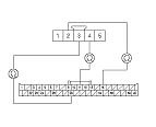
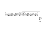
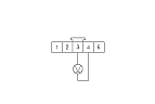
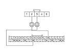
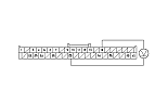
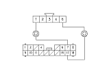
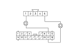
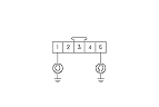
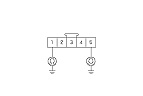
Disconnect power seat control unit connector A (40P).
-
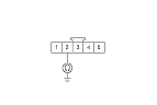
Disconnect the slide motor/position sensor 5P connector.
-
Check for continuity between power seat control unit connector A (40P) No. 11, No. 15, and No. 29 terminals and the slide motor/position sensor 5P connector No. 2, No. 3, and No. 4 terminals respectively.
|
YES
|
-
|
|
|
NO
|
-
|
Repair an open in the wire.■
|
|