|
DTC U0029:
F-CAN Communication Line Error
NOTE: Make sure the HDS communicates with the ECM/PCM and other vehicle systems. If it does not, go to DLC Circuit Troubleshooting:
-
Clear the DTCs with the HDS.
-
Turn the ignition switch to LOCK (0) and then back to ON (II).
-
Wait for 6 seconds or more.
-
Check for DTCs with the HDS.
|
YES
|
-
|
|
|
NO
|
-
|
Intermittent failure, the system is OK at this time. Check for loose or poor connections, or worn/shorted wires. If the connections are good,
check the battery condition
and the charging system.■
|
-
Turn the ignition switch to LOCK (0).
-
Disconnect the appropriate connector at each control unit in the table one at a time. Clear the DTC, then recheck for DTCs after each unit is disconnected.
|
Control Unit
|
Connector
|
|
ECM/PCM
|
R20A3 engine: connector A (44P)
K24Z3 engine: connector A (49P)
|
|
SRS unit
|
Connector A (39P)
|
|
Gauge control module
|
32P connector
|
|
VSA modulator-control unit
|
32P connector
|
|
Navigation unit
*1
|
32P connector
|
|
EPS control unit
|
28P connector
|
|
Yaw rate-lateral acceleration sensor
|
4P connector
|
|
ACC control unit
*2
|
20P connector
|
|
E-pretensioner unit
*2
|
Connector B (14P)
|
|
LKAS unit
*3
|
26P connector
|
|
*1:
|
With navigation
|
|
*2:
|
With ACC
|
|
*3:
|
With LKAS
|
|
Is DTC U0029 indicated with each individual unit disconnected?
|
|
YES
|
-
|
|
|
NO
|
-
|
Replace the control unit that was disconnected when DTC U0029 is not reset.■
|
-
Turn the ignition switch to LOCK (0).
-
Disconnect each control unit connectors in the table.
|
Control Unit
|
Connector
|
|
ECM/PCM
|
R20A3 engine: connector A (44P)
K24Z3 engine: connector A (49P)
|
|
SRS unit
|
Connector A (39P)
|
|
Gauge control module
|
32P connector
|
|
VSA modulator-control unit
|
32P connector
|
|
Navigation unit
*1
|
32P connector
|
|
EPS control unit
|
28P connector
|
|
Yaw rate-lateral acceleration sensor
|
4P connector
|
|
ACC control unit
*2
|
20P connector
|
|
E-pretensioner unit
*2
|
Connector B (14P)
|
|
LKAS unit
*3
|
26P connector
|
|
*1:
|
With navigation
|
|
*2:
|
With ACC
|
|
*3:
|
With LKAS
|
-
Disconnect the HDS from the data link connector.
-
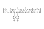
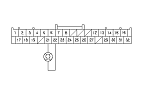
Check for continuity between body ground and the gauge control module 32P connector No. 21 and No. 22 terminals individually.
|
YES
|
-
|
A short to ground in the wire.■
|
|
NO
|
-
|
|
|