|
DTC 30:
Adaptive Cruise Control (ACC) Relay Circuit Malfunction
NOTE: Information marked with an asterisk (
*1
) applies to RHD model, and asterisk (
*2
) applies to LHD model.
-
Check the brake lights without pressing the brake pedal.
|
Are the brake lights off?
|
-
-
Check the brake lights without pressing the brake pedal.
|
Are the brake lights off?
|
|
YES
|
-
|
Intermittent failure. The system is OK at this time. Check for loose or poor connections.■
|
|
NO
|
-
|
|
-
|
Is the brake pedal position switch OK?
|
-
|
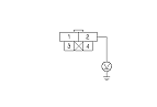
Is the relay circuit board OK?
|
|
YES
|
-
|
|
|
NO
|
-
|
Replace the under-hood fuse/relay box and recheck.■
|
-
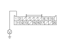
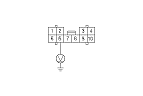
Disconnect the 4P connector from the brake pedal position switch.
-
Check for voltage between the brake pedal position switch 4P connector No. 2 terminal and body ground.
|
Is there battery voltage?
|
|
YES
|
-
|
Repair a short to power in the wire.■
|
|
NO
|
-
|
|
-
Turn the ignition switch to LOCK (0).
-
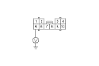
Disconnect the ACC unit 20P connector.
-
Turn the ignition switch to ON (II).
|