How to Troubleshoot the LKAS

LKAS Indicator (Orange)
When the LKAS system is OK, the ACC, LKAS indicators come on for about 2 seconds after turning the ignition switch to ON (II), then goes off.
When the LKAS system detects a problem while in operating, the LKAS system stops control, and the LKAS indicator comes on and stays on.
NOTE:
  • The EPS control unit does only the malfunction which related to LKAS system with the LKAS indicator, and the malfunction which related to EPS does a caution with the EPS indicator and LKAS indicator.
  • The LKAS system is communicating with the ECM/PCM, the VSA modulator control unit and the gauge control module by F-CAN. If a connected unit has malfunction, the LKAS system does not operate. In this case, both LKAS indicator and connected unit indicator come on and stay on (expect the gauge control module).

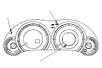
LKAS Activation Indicator (Green)
If the LKAS system is normal, the indicators come on with the main switch is ON, and goes off with the main switch is OFF.

Self-diagnostic Function
The LKAS system has a self-diagnostic function. If the self-diagnostic function detects a malfunction, the ACC system and the LKAS system stop control, turn on the ACC, LKAS indicator, and stores DTCs.

Multi-information Display (MID) Indication
If the LKAS system is normal, the LKAS indicate this operation on the multi-information display (MID) with the main switch is ON. When the system stops with the malfunction during LKAS control, it makes the LKAS OFF indicator come on. When returning normally about DTC 7 or DTC 8, the LKAS OFF indicator goes off.

Adaptive Cruise Control (ACC) Unit
The ACC unit uses input from the millimeter wave radar to controls the vehicle's speed and breaks to maintain a constant distance between the vehicle and other moving vehicles directly ahead.

Millimeter Wave Radar
The millimeter wave radar recognizes the position of the vehicle running ahead and detects the two vehicles speed differential.
The adaptive cruise control (ACC) unit receives these information from the millimeter wave radar.
The millimeter wave radar has also the error detect function, and sends signal to the ACC unit if an error is detected.

Millimeter Wave Radar Aiming
If the millimeter wave radar is removed or replaced, do the millimeter wave radar aiming procedure. If incomplete, the LKAS indicator come on.

LKAS Camera Aiming
If the LKAS camera is removed or replacement, do the LKAS camera aiming. If incomplete or failure of aiming stores DTC, the LKAS activation indicator come on.
There are Static Aiming and Dynamic Aming, and they need to be done in that order.

LKAS Camera
LKAS camera sends the lane image which was gotten by the LKAS camera to the LKAS control unit.
Also, it is equipped with an error detection feature and it sends error data to the LKAS control unit when detecting a malfunction.

EPS Control Unit
When the malfunction of the EPS control occurs during the LKAS system operation, it makes EPS, LKAS indicators come on. When the malfunction of the LKAS control relations, it doesn't indicate the EPS indicator, and indicate of LKAS indicator and the LKAS control of EPS is canceled. After LKAS cancellation, depending on the malfunction which detected usual EPS control by the doing, it continues and it stops assist. When the EPS indicator come on during LKAS system operation, check the DTC of EPS, and when the LKAS indicator come on, check the LKAS system DTC and it does a trouble diagnosis.

CAN Communication
LKAS system is composed of LKAS control unit, ACC unit, LKAS camera and LKAS control unit and ACC unit are sending and receiving a dater by the other control system inter-unit and the multiplex-communication system which used F-CAN (Between LKAS control unit and LKAS camera, special CAN communicates).
If there is a communication malfunction between the system which is related with ACC sysytem, LKAS system does not do LKAS contol and ACC system even if it is normal. Other system indicator and the LKAS indicator comes on.

How to Retrieve DTCs
  1. With the ignition switch to LOCK (0), connect the HDS to the data link connector (DLC) (A) under the left side of the dashboard.
  1. Turn the ignition switch to ON (II), and follow the prompts on the HDS to display the DTC(s) on the screen. After determining the DTC, refer to the DTC Troubleshooting.
    NOTE: See the HDS Help menu for specific instructions.
  1. Make sure the HDS communicates with the vehicle and the ACC unit. If it does not communicate, troubleshoot the DLC circuit.
  1. Follow the prompts on the HDS to display the DTC(s) on the screen. After determining the DTC, refer to the DTC troubleshooting.
    NOTE: See the HDS Help menu for specific instructions.

How to Clear DTCs
NOTE: You cannot clear the DTCs manually.
  1. With the ignition switch to LOCK (0), connect the HDS to the data link connector (DLC) (A) under the left side of the dashboard.
  1. Turn the ignition switch to ON (II), and clear the DTC(s) by following the screen prompts on the HDS.
    NOTE: See the HDS Help menu for specific instructions.
  1. Make sure the HDS communicates with the vehicle and the ACC unit. If it does not communicate, troubleshoot the DLC circuit.
  1. Clear the DTC(s) by following the screen prompts on the HDS.
    NOTE: See the HDS Help menu for specific instructions.