|
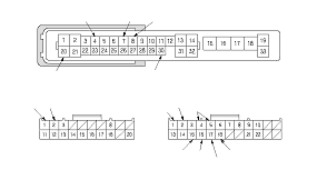
R15 · R4
|
ORN · BLK
|
Wiper switch ON at INT or LO position
|
Measure the voltage between the R15 and the R4 terminals:
There should be less than 1 V.
|
|
|
Wiper switch OFF
|
Measure the voltage between the R15 and the R4 terminals:
There should be more than 5 V.
|
|
|
R16 · R4
|
WHT · BLK
|
Wiper switch ON at LO or HI position
|
Measure the voltage between the R16 and the R4 terminals:
There should be less than 1 V.
|
|
|
Wiper switch OFF
|
Measure the voltage between the R16 and the R4 terminals:
There should be more than 5 V.
|
|
|
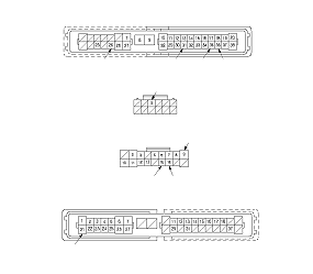
R17 · R4
|
GRN · BLK
|
Wiper switch ON at MIST position
|
Measure the voltage between the R17 and the R4 terminals:
There should be less than 1 V.
|
|
|
Wiper switch OFF
|
Measure the voltage between the R17 and the R4 terminals:
There should be more than 5 V.
|
|
|
R18 · R4
|
YEL · BLK
|
Washer switch ON
|
Measure the voltage between the R18 and the R4 terminals:
There should be less than 1 V.
|
|
|
Washer switch OFF
|
Measure the voltage between the R18 and the R4 terminals:
There should be more than 5 V.
|
|
|
R1 · R4
|
BLU · BLK
|
Intermittent dwell timer turned
|
Check resistance between the R1 and R4 terminals:
There resistance should vary between 0 to 1 kΩ.
|
|