Power Relay Test

Use this chart to identify the type of relay, then do the test listed for it.
Relay
Test
Accessory power socket relay
Normally-open type
A/C compressor clutch relay
Blower motor relay
Cigarette lighter relay
Driver's seat heater relay (high)
ETCS control relay
Front passenger's seat heater relay (high)
Headlight washer relay
Horn relay
Ignition coil relay
PGM-FI main relay 1 (FI MAIN)
PGM-FI main relay 2 (FUEL PUMP)
PGM-FI subrelay
Radiator fan relay
Rear window defogger relay
Security horn relay
Starter cut relay
Driver's seat heater relay (low)
Five-terminal type
Front passenger's seat heater relay (low)
Left side super locking LOCK relay
Right side super locking LOCK relay
Super locking UNLOCK relay
Daytime running lights relay

Normally-open type
Check for continuity between the terminals:
  • There should be continuity between the No. 1 and No. 2 terminals when battery power is connected to the No. 4 terminal, and body ground is connected to the No. 3 terminal.
  • There should be no continuity between the No. 1 and No. 2 terminals when power is disconnected.

Five-terminal type
Check for continuity between the terminals:
  • There should be continuity between the No. 1 and No. 2 terminals when battery positive terminal is connected to the No. 5 terminal, and battery negative terminal is connected to the No. 3 terminal.
  • There should be continuity between the No. 1 and No. 4 terminals when power is disconnected.

Relay Circuit Board Test
The relay circuit board contains these relay circuits:
  • ACC relay
  • A/C condenser fan relay
  • Fan control relay
  • Wiper motor relay
  • Wiper intermittent relay
  • Wiper high/low relay
ACC relay, A/C condenser fan relay, Fan control relay
Wiper motor relay, Wiper intermittent relay, Wiper high/low relay

  1. Disconnect the connectors B (14P) and C (10P) from the under-hood fuse/relay box (the relay circuit board).
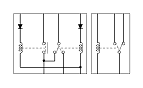
  1. Test each relay circuit as shown:
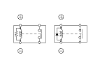
    ACC relay circuit test:
    When power is connected to the C9 terminal and ground is connected to the C7 terminal, there should be continuity between the C5, C6 and C8 terminals.
    When power is disconnected, there should be no continuity between the C5, C6 and C8 terminals, and there should be continuity between the C2 and C8 terminals.
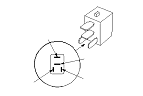
    A/C condenser fan relay circuit test:
    When power is connected to the B7 terminal and ground is connected to the C10 terminal, there should be continuity between the C1 and C4 terminals.
    When power is disconnected, there should be no continuity between the C1 and C4 terminals.
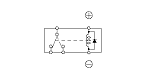
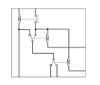
    Fan control relay circuit test:
    When power is connected to the B2 terminal and ground is connected to the C10 terminal, there should be continuity between the B11 and B1 terminals.
    When power is disconnected, there should be no continuity between the B11 and B1 terminals, and there should be continuity between the B11 and C4 terminals.
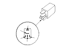
    Wiper motor relay circuit test:
    When power is connected to the B3 and B13 terminals and ground is connected to the B4 and B14 terminals, there should be continuity between the B3 and B6 terminals.
    When power is disconnected, there should be no continuity between the B3 and B6 terminals.
    Wiper intermittent relay circuit test:
    When power is connected to the B3 and B13 terminals and ground is connected to the B4 and B14 terminals, there should be voltage B3 and B6 terminals.
    When power is disconnected from the B3 and B13 terminals, there should be continuity between B13 and B6 terminals.
    Wiper high/low relay circuit test:
    When power is connected to the B3 and B13 terminals and ground is connected to the B4 and B12 terminals, there should be voltage B3 and B5 terminals.
    When power is disconnected from the B3 and B13 terminals, there should be continuity between B13 and B6 terminals.
  1. If any of these relay circuit fails the test, replace the relay circuit board.