How to Troubleshoot the Body Electrical

Tips and Precautions

Before Troubleshooting

  1. Check applicable fuses in the appropriate fuse/relay box.
  1. Check the battery for damage, state of charge, and clean and tight connections.
    • Do not quick-charge a battery unless the battery ground cable has been disconnected, otherwise you will damage the alternator diodes.
    • Do not attempt to crank the engine with the battery ground cable loosely connected or you will severely damage the wiring.


Handling Connectors

  • Make sure the connectors are clean and have no loose wire terminals.
  • Make sure multiple cavity connectors are packed with dielectric grease (except watertight connectors).
  • All connectors have push-down release type locks (A).

  • Some connectors have a clip on their side used to attach them to a mount bracket on the body or on another component. This clip has a pull type lock.
  • Some mounted connectors cannot be disconnected unless you first release the lock and remove the connector from its mount bracket (A).

  • Never try to disconnect connectors by pulling on their wires; pull on the connector halves instead.
  • Always reinstall plastic covers.

  • Before connecting connectors, make sure the terminals (A) are in place and not bent.

  • Check for loose retainer (A) and rubber seals (B).

  • The backs of some connectors are packed with dielectric grease. Add grease if necessary. If the grease is contaminated, replace it.

  • Insert the connector all the way and make sure it is securely locked.
  • Position wires so that the open end of the cover faces down.


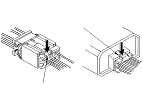
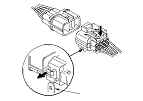
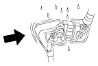
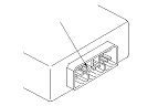
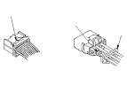
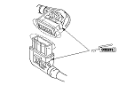
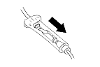
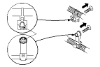
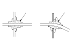
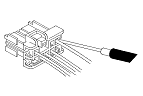
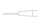
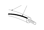
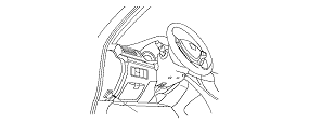
Handling Wires and Harnesses

  • Secure wires and wire harnesses to the frame with their respective wire ties at the designated locations.
  • Remove clips carefully; don't damage their locks (A).

  • After installing harness clips, make sure the harness doesn't interfere with any moving parts.
  • Keep wire harnesses away from exhaust components and other hot parts, from sharp edges of brackets and holes, and from exposed screws and bolts.
  • Seat grommets in their grooves properly (A). Do not leave grommets distorted (B).


Testing and Repairs

  • Do not use wires or harnesses with broken insulation. Replace them or repair them by wrapping the break with electrical tape.
  • Never attempt to modify, splice, or repair SRS wiring. If there is an open or damage is SRS wiring or terminals, replace the harness.
  • After installing parts, make sure that no wires are pinched under them.
  • When using electrical test equipment, follow the manufacturer's instructions and those described in this manual.
  • If possible, insert the probe of the tester from the wire side (except waterproof connector).

  • Use back probe adaptor 07TAZ-001020A.
  • Refer to the instructions in the Honda Terminal Kit for identification and replacement of connector terminals.

Five-step Troubleshooting
  1. Verify The Complaint:
    Turn on all the components in the problem circuit to verify the customer complaint. Note the symptoms. Do not begin disassembly or testing until you have narrowed down the problem area.
  1. Analyze The Schematic:
    Look up the schematic for the problem circuit. Determine how the circuit is supposed to work by tracing the current paths from the power feed through the circuit components to ground. If several circuits fail at the same time, the fuse or a ground is a likely cause.
    Based on the symptoms and your understanding of the circuit operation, identify one or more possible causes of the problem.
  1. Isolate The Problem By Testing The Circuit:
    Make circuit tests to check the diagnosis you made in Step 2 . Keep in mind that a logical, simple procedure is the key to efficient troubleshooting. Test for the most likely cause of failure first. Try to make tests at points that are easily accessible.
  1. Fix The Problem:
    Once the specific problem is identified, make the repair. Be sure to use proper tools and safe procedures.
  1. Make Sure The Circuit Works:
    Turn on all components in the repaired circuit in all modes to make sure you've fixed the entire problem. If the problem was a blown fuse, be sure to test all of the circuits on the fuse. Make sure no new problems turn up and the original problem does not recur.

Wire Color Codes
The following abbreviations are used to identify wire colors in the circuit schematics:
WHT. 
White
YEL. 
Yellow
BLK. 
Black
BLU. 
Blue
GRN. 
Green
RED. 
Red
ORN. 
Orange
PNK. 
Pink
BRN. 
Brown
GRY. 
Gray
PUR. 
Purple
LT BLU. 
Light Blue
LT GRN. 
Light Green

The wire insulation has one color or one color with another color stripe. The second color is the stripe.

Troubleshoot the B-CAN Circuit Related Problems
How to check for DTCs with the HDS (preferred method)
The HDS can check the F-CAN and B-CAN communication status, read and clear the DTCs, display the data list, and perform function test.
Check for DTCs
  1. Connect the HDS to the data link connector (A) located under the driver's side of the dashboard.
  1. Turn the ignition switch to ON (II).
  1. Make sure the HDS communicates with vehicle.
    NOTE: If the HDS does not communicate with the vehicle, troubleshoot the DLC circuit.
  1. Select the BODY ELECTRICAL, then select the desired TEST MODE menu, and check the DTCs. If the DTCs do not pertain to the select menu, select the All DTC Check icon to view all Body DTCs.
    NOTE: For specific operations, refer to the HDS user's manual.
  1. If any DTCs are indicated, go to the indicated DTCs troubleshooting.
    NOTE: If the DTC U1280 is stored, troubleshoot the DTC U1280 first.

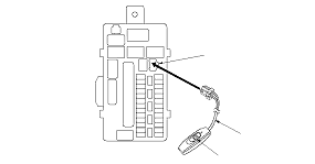
How to check for DTCs without the HDS (Use only if the HDS is unavailable)
Special Tools Required

MPCS short connector
 07WAZ-0010100
If the HDS is unavailable, using the following method, you can check the B-CAN communication status, DTCs, and some F-CAN communication status related with the gauge control module.

Check for DTCs

  1. Turn the ignition switch to ON (II).
  1. Connect the MPCS short connector (A) to the MICU service check connector (B), and turn the switch (C) ON.

  1. After 5 to 10 seconds, the DTCs which have been detected and stored individually by various B-CAN unit, will be indicates one by one on the odo/trip display if the communication line between the driver's MICU and the gauge control module is OK. To scroll through the DTCs, press the select/reset button.
The unit that has stored the code can be identified by the number shown on the odometer display.
Control Unit
Control Unit I.D. Number
Driver's MICU
13
Passenger's MICU
14
Door multiplex control unit
30
Gauge control module
50
Heater control unit/Climate control unit
51
Automatic lighting/rain sensor
71
Headlight leveling control unit
75
Hands Free Telephone control unit
94
Parking and back-up sensor control unit
9A
Power seat control unit
95
Immobilizer-keyless control unit
96

NOTE: Also you can check the B-CAN communication status by following methods:

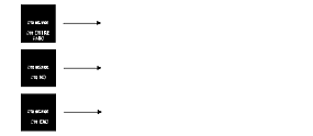
How to Clear the DTCs with the HDS
  1. Connect the HDS to the data link connector (A) located under the driver's side of the dashboard.
  1. Turn the ignition switch to ON (II).
  1. Clear the DTCs with the HDS.
  1. Turn the ignition switch to LOCK (0), and disconnect the HDS from the data link connector (DLC).

How to Clear the DTCs without the HDS
  1. While in DTCs indication status, press and hold the SELECT/RESET switch for more than 10 seconds.
  1. Turn the MPCS short connector switch off, and disconnect the connector from the MICU service check connector.
  1. Turn the ignition switch to LOCK (0).

HDS Inputs and Commands
Certain inputs happen so quickly that the HDS can not update fast enough. Hold the switch that is being tested while monitoring the Data List. This should give the HDS time to update the signal on the Data List. Because the HDS software is updated to support the release for newer vehicles it is not uncommon to see system function tests that are not supported. Make sure that the most current software is loaded.

Input:

System Menu
Data List
Data List Indication
Gauge
Cruise Control Main Switch (ACC switch)
OFF/ON
Cruise Control Set Switch
OFF/ON
Cruise Control Resume Switch
OFF/ON
VSA/TCS Off Switch
OFF/ON
Gauge Select/Reset Switch
OFF/ON
Parking Brake Switch
OFF/ON
Brake Fluid Level Switch
OFF/ON
Fuel Sending Unit Input 1
deg
Fuel Sending Unit Input 2
V
VSA/TCS Active Indicator
OFF/ON
VSA/TCS Indicator (Warning)
OFF/ON
ABS Indicator
OFF/ON
EBD Indicator (Electronic Brake Distribution)
OFF/ON
Cruise Control Main Switch Indicator
OFF/ON
MIL Indicator
OFF/ON
Low Oil Pressure Indicator
OFF/ON
Charging System Indicator
OFF/ON
CRUISE Main Switch Lamp
OFF/ON
High Beam Indicator
OFF/ON
Parking Light ON Indicator
OFF/ON
Low Fuel Warning Indicator
OFF/ON
Security Indicator
OFF/ON
Fog Light Indicator
OFF/ON
Auto-Light Trouble Lamp
OFF/ON
Seat Belt Indicator
OFF/ON
Speed Indicator (km/h) Command
km/h
Speed Indicator (mph) Command
mile/h


HDS Inputs and Commands

Input:

System Menu
Data List
Data List Indication
Lighting
Passing Input Signal
OFF/ON
Headlight ON Input Signal
OFF/ON
Driver's Door Switch
OFF/ON
Hazard Switch
OFF/ON
Headlight Switch (OFF)
OFF/ON
Headlight Switch (PARKING)
OFF/ON
Headlight Switch (HEADLIGHT)
OFF/ON
Headlight Switch (AUTO)
OFF/ON
Headlight Switch (High Beam)
OFF/ON
Headlight Switch (PASSING)
OFF/ON
Turn Signal Switch (LEFT)
OFF/ON
Turn Signal Switch (RIGHT)
OFF/ON
Fog Light Switch
OFF/ON
Rear Fog Light Switch
OFF/ON
Interior Light Command
OFF/ON
Left Turn Signal Command
OFF/ON
Right Turn Signal Command
OFF/ON
Rear Fog Light Command
OFF/ON
DR Courtesy Light Output
OFF/ON
RD Courtesy Light Output
OFF/ON
Headlight Command
OFF/ON
Headlight High Beam Command
OFF/ON
Parking Light Command
OFF/ON
Fog Light Command
OFF/ON
Autolight Sensor Input Voltage
V
Autolight Sensor Malfunction Detection Voltage Max
V
Autolight Sensor Malfunction Detection Voltage Min
V
Headlight Cleaner Command
OFF/ON
Autolight Small Command
OFF/ON
Autolight Headlight Command
OFF/ON
Autolight Warning Command
OFF/ON
Autolight Headlight Backup Line Command
OFF/ON
AS Courtesy Light Output
OFF/ON
RA Courtesy Light Output
OFF/ON


HDS Inputs and Commands

Input:

System Menu
Data List
Data List Indication
Door Locks
Driver's Door Key Cylinder Switch (LOCK)
OFF/ON
Driver's Door Key Cylinder Switch (UNLOCK)
OFF/ON
Driver's Door Lock Switch (LOCK)
OFF/ON
Driver's Door Lock Switch (UNLOCK)
OFF/ON
Driver's Door Lock Knob Switch (LOCK)
OFF/ON
Driver's Door Lock Knob Switch (UNLOCK)
OFF/ON
Driver's Door Switch
OFF/ON
Driver's Rear Door Switch
OFF/ON
Driver's Rear Door Lock Knob Switch (UNLOCK)
OFF/ON
Door LOCK Command
OFF/ON
Door UNLOCK Command
OFF/ON
Driver's Door UNLOCK Command
OFF/ON
Front Passenger's Door Switch
OFF/ON
Passenger's Rear Door Switch
OFF/ON
Passenger's Rear Door Lock Knob Sw. (UNLOCK)
OFF/ON
Door LOCK Command
OFF/ON
Door UNLOCK Command
OFF/ON


HDS Inputs and Commands

Input:

System Menu
Data List
Data List Indication
Keyless
Driver's Door Key Cylinder Switch (LOCK)
OFF/ON
Driver's Door Key Cylinder Switch (UNLOCK)
OFF/ON
Driver's Door Lock Switch (LOCK)
OFF/ON
Driver's Door Lock Switch (UNLOCK)
OFF/ON
Driver's Door Lock Knob Switch (LOCK)
OFF/ON
Driver's Door Lock Knob Switch (UNLOCK)
OFF/ON
Driver's Door Switch
OFF/ON
Driver's Rear Door Switch
OFF/ON
Trunk Lid/Tailgate Switch
OFF/ON
Driver's Rear Door Lock Knob Switch (UNLOCK)
OFF/ON
Door LOCK Command
OFF/ON
Door UNLOCK Command
OFF/ON
Driver's Door UNLOCK Command
OFF/ON
Trunk Lid Release Command
OFF/ON
Front Passenger's Door Switch
OFF/ON
Passenger's Rear Door Switch
OFF/ON
Passenger's Rear Door Lock Knob Sw. (UNLOCK)
OFF/ON
Door LOCK Command
OFF/ON
Door UNLOCK Command
OFF/ON
Power Windows
P/W Main Switch
OFF/ON
P/W Master Switch (Driver's Window AUTO)
OFF/ON
P/W Master Switch (Driver's Window UP)
OFF/ON
P/W Master Switch (Driver's Window DOWN)
OFF/ON
P/W Master Sw. (Front Passenger's Window UP)
OFF/ON
P/W Master Sw. (Front Passenger's Window DOWN)
OFF/ON
P/W Master Switch (Left Rear Window UP)
OFF/ON
P/W Master Switch (Left Rear Window DOWN)
OFF/ON
P/W Master Sw. (Right Rear Window UP)
OFF/ON
P/W Master Sw. (Right Rear Window DOWN)
OFF/ON
P/W Master Sw. (Passenger's Window AUTO)
OFF/ON
Driver's P/W Motor Pulse A
NOT EXIST/EXIST
Driver's P/W Motor Pulse B
NOT EXIST/EXIST
Driver's P/W Motor Command
OFF/UP/DOWN
Driver's Door Switch
OFF/ON
Power Window Timer Output
OFF/ON
Front Passenger's Door Switch
OFF/ON
Power Window Timer Output
OFF/ON


HDS Inputs and Commands

Input:

System Menu
Data List
Data List Indication
Wipers
Rain Sensing Information
Normal condition, Need to check, System error warning
Brake Pedal Position Switch
OFF/ON
Windshield Wiper Switch (LOW)
OFF/ON
Windshield Wiper Switch (HIGH)
OFF/ON
Windshield Wiper Switch (MIST)
OFF/ON
Windshield Wiper Switch (INT)
OFF/ON
Windshield Washer Switch
OFF/ON
Windshield Wiper Motor PARK Switch
OFF/ON
Windshield Wiper Motor HI Command
OFF/ON
Windshield Wiper Motor LO Command
OFF/ON
Headlight Washer switch
OFF/ON
Windshield Washer Motor Command
OFF/ON
Security
Driver's Door Key Cylinder Switch (LOCK)
OFF/ON
Driver's Door Key Cylinder Switch (UNLOCK)
OFF/ON
Driver's Door Lock Switch (LOCK)
OFF/ON
Driver's Door Lock Switch (UNLOCK)
OFF/ON
Driver's Door Lock Knob Switch (LOCK)
OFF/ON
Driver's Door Lock Knob Switch (UNLOCK)
OFF/ON
Ignition Key Cylinder Switch
OFF/ON
Driver's Door Switch
OFF/ON
Driver's Rear Door Switch
OFF/ON
Trunk Lid/Tailgate Switch
OFF/ON
Driver's Rear Door Lock Knob Switch (UNLOCK)
OFF/ON
Radio Switch
OFF/ON
Hazard Switch
OFF/ON
Hood Switch
OFF/ON
Door LOCK Command
OFF/ON
Door UNLOCK Command
OFF/ON
Driver's Door UNLOCK Command
OFF/ON
Trunk Lid Release Command
OFF/ON
Headlight Command
OFF/ON
Headlight High Beam Command
OFF/ON
Parking Light Command
OFF/ON
Horn Command
OFF/ON
Front Passenger's Door Switch
OFF/ON
Passenger's Rear Door Switch
OFF/ON
Passenger's Rear Door Lock Knob Sw. (UNLOCK)
OFF/ON
Radio Switch
OFF/ON
Door LOCK Command
OFF/ON
Door UNLOCK Command
OFF/ON
Headlight Command
OFF/ON
Headlight High Beam Command
OFF/ON
Parking Light Command
OFF/ON


HDS Inputs and Commands

Input:

System Menu
Data List
Data List Indication
Climate control
A/C Pressure Switch/Thermal Protector
OFF/ON
Rear Defroster Input Switch
OFF/ON
Rear Defroster Output Switch
OFF/ON
Headlight leveling
Front Height Sensor Value
Rear Height Sensor Value
Adjust Sensor Value
Height Sensor Minimum Value
Height Sensor Maximum Value
Passing Input Signal
OFF/ON
Headlight ON Input Signal
OFF/ON
Vehicle Speed Input Signal
OFF/ON
Auto Leveling Warning Command
OFF/ON
Height Sensor Input Signal
OFF/ON
Adjust Output Signal
OFF/ON
Auto Light Leveling Calibration Completion Command


Output:

System Menu
HDS Description
Note
Climate control
Rear defroster RLY
Outputs for 60 seconds
Rear Defogger
Operates a relay of Rear defroster for 60 seconds
Headlight leveling
The reflector is moved one time up and down
Warning lamp
Warning lamp
Door locks
LOCK all doors
Outputs LOCK signal 1 time (0.6 sec) to all door
UNLOCK all doors
Outputs UNLOCK signal 1 time (0.6 sec) to all door
UNLOCK driver's side door
Outputs UNLOCK signal 1 time (0.6 sec) to driver side door
Keyless
Trunk Lid/Tailgate Release Command
Unlock trunk
Lighting
Interior Light Command
Illuminates for 30 seconds
Hazard flasher (Turn left and right)
Blinks turn signal (left and right) for 15 seconds
LEFT Turn Signal Command
Blinks for 5 seconds
RIGHT Turn Signal Command
Blinks for 5 seconds
Headlight Command
Operates headlight (low) for 15 seconds
Headlight HIGH Beam Command
Operates headlight (high) for 15 seconds
Fog Light
Operates a relay of front fog light for 15 seconds
Courtesy light (DR)
Illuminates for 30 seconds
Small light
Operates small lights for 15 seconds
Courtesy LT RD
Outputs for 30 seconds
Rear Fog Light
Illuminates for 30 seconds
Headlight Backup
Outputs for 15 milliseconds
Headlight Cleaner
Outputs operation 1 time (for 750 milliseconds)
Courtesy light (AS)
Illuminates for 30 seconds
Courtesy LT RA
Outputs for 30 seconds
Headlight Command
Operates for 15 seconds
Headlight HIGH Beam Command
Operates for 15 seconds
Parking Light Command
Operates for 15 seconds
Fog Light
Operates for 15 seconds
Rear Fog Lamp
Illuminates for 30 seconds
Cargo Area Light
Illuminates for 30 seconds
Power windows
Power window RLY Rr
Outputs for 30 seconds
Power window RLY Rr
Outputs for 30 seconds
Driver's Window Up
Drives for 3 seconds
Driver's Window Down
Drives for 3 seconds
Front Passenger's Window Up
Drives for 3 seconds
Front Passenger's Window Down
Drives for 3 seconds
Left Rear Window Up
Drives for 3 seconds
Left Rear Window Down
Drives for 3 seconds
Right Rear Window Up
Drives for 3 seconds
Right Rear Window Down
Drives for 3 seconds
Security
Horn Command
Operates horn for 1 second
Horn Command
Operates horn for 1 second
Wiper
Windshield Wiper Motor LOW Command
Operates windshield wiper for 5 seconds (low speed)
Windshield Wiper Motor HIGH Command
Operates windshield wiper for 5 seconds (high speed)
Windshield Washer Command
Operates windshield washer for 5 seconds
Windshield Wiper Motor LOW Command
Operates windshield wiper for 5 seconds (low speed)
Windshield Wiper Motor HIGH Command
Operates windshield wiper for 5 seconds (high speed)
Windshield Washer Command
Operates windshield washer for 5 seconds
Auto Wiper Test
Outputs intermittent wiper signal (1 time)
Driving position memory system
Power Seat: Slide Motor-Full FORWARD
Power Seat: Slide Motor-Full BACKWARD
Power Seat: Front UP-DOWN Motor-Full UP
Power Seat: Front UP-DOWN Motor-Full DOWN
Power Seat: Rear UP-DOWN Motor-Full UP
Power Seat: Rear UP-DOWN Motor-Full DOWN
Power Seat: Recline Motor-Full FORWARD
Power Seat: Recline Motor-Full BACKWARD
Power Seat: Memory Buzzer-5 seconds

When an ECU is unable to communicate with the other ECUs on the CAN circuit, the other control units will set loss of communication DTCs. Use this chart to find the control unit that is not communicating.
  1. Find the Transmitting Control Unit that is in the same row as all of the loss of communication DTCs retrieved.
  1. Do the input test for the transmitting control unit.

BUS OFF and Internal Error Codes

DTC type
Related Unit
Drive's MICU
Passenger's MICU
Gauge control module
Door multiplex control unit
Immobilizer-keyless control unit
Heater control unit/ Climate control unit
Headlight leveling control unit
Automatic lighting/Rain sensor
Power seat control unit
Hands Free Telephone control unit
Parking and back-up sensor control unit
BUS OFF
U1280
U1280
U1280
U1280
U1280
U1280
U1280
U1280
U1280
U1280
U1280
ECU (EEPROM) Error
B10A2
B11A2
B1152
Driver's MICU
TX
U1282
U1282
U1282
U1282
U1282
U1282
U1282
U1282
Passenger's MICU
U1283
TX
U1283
U1283
Gauge control module
U0155
U0155
TX
U0155
U0155
U0155
U0155
U0155
U0155
Door multiplex control unit
U0199
TX
U0199
Heater control unit/ Climate control unit
U0164
TX
TX
ECM/PCM
U0100
SRS unit
U0151
ACC control unit
U0104
VSA modulator-control unit
U0122
EPS control unit
U0131


TX:
Transmitting unit does not set a loss of communication DTC.

NOTE: In order for the driver's MICU to verify the communication with the rain sensor (with automatic wiper), after the battery terminal(s) have been disconnected, connect the rain sensor 6P connector before reconnecting the battery terminal(s) and turn the ignition switch ON (II). Since only the rain sensor is determined equipped or unequipped by the presence of communication, when the connector is disconnected, even the equipped vehicle is determined as unequipped.