|
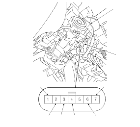
7
|
BRN
|
LG
|
Under all conditions
|
Check for continuity to ground: There should be continuity.
|
-
Poor ground (G101)
-
An open in the wire
|
|
1
|
WHT
|
VBU
|
Under all conditions
|
Measure the voltage to ground: There should be battery voltage.
|
|
|
2
|
YEL
|
IG1
|
Ignition switch ON (II)
|
Measure the voltage to ground: There should be battery voltage.
|
|
|
3
|
BLU
|
B-CAN LO
|
Disconnect the gauge control module 32P connector
|
Check for continuity between the terminal and the gauge control module 32P connector No. 23 terminal: There should be continuity.
|
An open in the wire
|
|
Disconnect driver's under-dash fuse/relay box connector P (20P)
|
Check for continuity between the terminal and driver's under-dash fuse/relay box connector P (20P) No. 5 terminal: There should be continuity.
|
An open in the wire
|
|
4
|
PNK
|
B-CAN HI
|
Disconnect the gauge control module 32P connector
|
Check for continuity between the terminal and the gauge control module 32P connector No. 24 terminal: There should be continuity.
|
An open in the wire
|
|
Disconnect driver's under-dash fuse/relay box connector P (20P)
|
Check for continuity between the terminal and driver's under-dash fuse/relay box connector P (20P) No. 6 terminal: There should be continuity.
|
An open in the wire
|
|
6
*1
|
LT GRN
|
IMOCD (S-NET)
|
Disconnect ECM/PCM connector A (49P)
*3
, then ignition switch ON (II)
|
Measure the voltage to ground: There should be battery voltage.
|
|
|
Check for continuity between the terminal and ECM/PCM connector A (49P) No. 46 terminal: There should be continuity.
|
An open in the wire
|
|
|
Measure the resistance between the terminal and body ground: There should be more than 50 kΩ.
|
|
|
6
*2
|
LT GRN
|
IMOCD (S-NET)
|
Disconnect ECM/PCM connector A (44P)
*3
, then ignition switch ON (II)
|
Measure the voltage to ground: There should be battery voltage.
|
|
|
Check for continuity between the terminal and ECM/PCM connector A (44P) No. 44 terminal: There should be continuity.
|
An open in the wire
|
|
|
Measure the resistance between the terminal and body ground: There should be more than 50 kΩ.
|
|