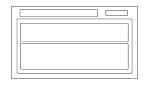
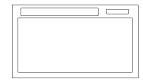
Navigation System Diagnostic Mode
|
Start-up procedure and Diagnostic Menu
There are two ways to enter the diagnostic mode:
|

|
|
Icon Color Information
|
||||||||||||||||||||||||||||||||||||||||||||||||||||||||||||||||||||||||||||||||||||||||||||||||||||||
|
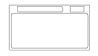
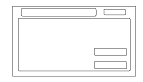
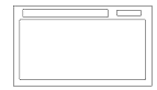
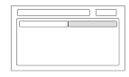
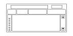
Factory diagnostic screen In Line Diag
NOTE: If the vehicle left the factory in the factory diagnostic mode, you will see this screen every time you turn on the ignition.
When a navigation control unit is powered up for the first time at the factory or after replacement with a new or remanufactured navigation unit, the factory diagnosis screen (In Line Diag) shows up. Normally the factory does the steps necessary to verify proper operation and terminate the factory diagnostic.
Until the proper confirmation sequence is done, the screen will show up every time the vehicle is started.
Follow the steps below to prevent the screen from showing up in the future:
|
KG and KE models
KQ model
|
|
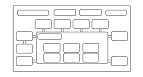
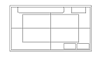
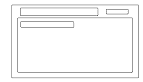
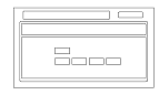
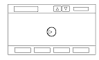
Monitor Check
Overview of display unit
These screens allow you to troubleshoot the display unit. Select the item you want to troubleshoot, and follow the diagnostic instructions.
|
|
|
Detailed Information & Settings
These section allows you to run a specific diagnostic and allows additional setting choices for some screens that are not shown when selecting an icon from the System Links screen.
When the menu item Detail Information & Setting is selected, the main diagnosis menu is displayed.
|
|
|
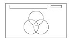
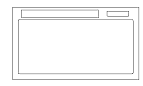
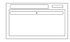
RGB Color
This screen verifies that the display unit is receiving the video (R, G, B and Composite sync) signals properly. The three primary colors should all be shown without distortion. The combination of all three should produce a central white section.
If any of the colors are missing, troubleshoot for the color signal.
If the picture has lines in it or rolls horizontally, or vertically, troubleshoot for a Composite sync problem.
|
|
|
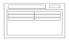
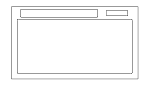
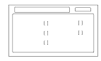
Gray Tone
This screen diagnoses problems with contrast. You should be able to see the changes from bar to bar across the scale. It is normal for the two bars on either side to appear the same. If you can't see changes from bar to bar, replace the navigation unit.
|
|
|
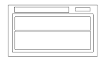
Black Raster
This diagnostic screen checks for pixels that may be stuck on. The entire display must be black. Is pixels are stuck on, replace the navigation unit.
|

|
|
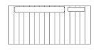
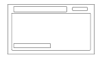
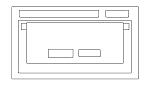
Color Pattern
The chart below shows the colors being used for the map and menu screens. This is for factory use only. To check the color signal use the RGB Color diagnostic found under the Monitor Check.
|
|
|
White Raster
This diagnostic screen checks for pixels that may be dead (off). The entire display must be white. If there are dead pixels, replace the navigation unit.
|
|
|
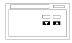
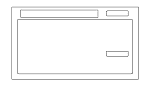
Monitor Adjustment
This allows you to center the navigation display. Use the joystick to move the picture up/down or left/right. It is unlikely that you will ever need to adjust the monitor position. The Default button will reset the display position to factory specifications.
|
|
|
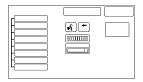
Unit Check (Quick Check)
Some of the tests and screens that are displayed under the Unit Check are different from the more detailed checks listed in other areas of this service manual.
To start the test, select the item you want to check.
|
KG and KE models
KQ model
|
|
Display
This diagnostic does additional checks on the communication bus between the control unit and the display. In addition, the internal electronics functionality are confirmed.
|
|
|
Radio
If NG is indicated, check for loose audio unit connectors.
|
|
|
GPS
If GPS indicates NG (ANT), then check the entire GPS antenna wire from the navigation unit to the antenna. If the wire is crushed or damaged, try a known good antenna. If this diagnostic reads OK, then order a new GPS antenna. If the diagnostic still reads NG (ANT), then replace the navigation unit.
Select information to see the GPS satellite details.
|
|
|
ECU Info.
This screen looks for problems in the navigation unit. When you initiate this diagnosis, the navigation unit may delay up to a minute while the diagnosis runs.
NOTE: Do not try to end this diagnostic by pressing OK or Mem clear before it finishes, otherwise the system may reboot.
|
|
|
Rear Camera
|
|
|
PC Card info. (KQ model)
There is no PC Card in the PC slot, and the screen should say, ‘‘PC Card is not inserted''.
NOTE: Do not insert any card or object into the slot.
|
|
|
If the factory provides a PC card and instructs you to insert a card, then the screen displays the Manufacturer, and Product Name as shown in the following screen.
|
|
|
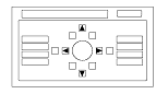
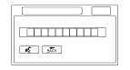
Hard Key
This diagnostic tests the interface dial, and the buttons that surround it. For this model, the interface dial and buttons do not use the GA-Net bus for communications.
To complete the test, touch each button on the vehicle's control panel, and move the interface dial to each indicated position. As each function is tested, the corresponding button on the display should highlight.
To exit, push in and hold the selector knob.
NOTE: You cannot use the onscreen return button to exit this function
|
|
|
Yaw Sensor
This screen gives a quick test of the yaw sensor functionality based on the two voltages Sensor and Offset. For more information see the Yaw Sensor Diagnostic.
|
|
|
DVD
This diagnostic tests the navigation DVD reader.
|
|
|
Aircon
This diagnostic tests the climate bus connection (AC-SI and AC-SO) between the navigation unit and climate control unit. Make sure the engine is running for this test.
|
|
|
HFT (KG and KE models)
This checks the 4 wire communication bus between the HFT and the navigation unit.
|
|
|
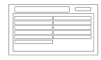
TMC Status (KG and KE models)
This screen displays a state about the RDS-TMC reception.
Frequency: Frequency receiving in this time.
Field Strength: Display reception sensitivity with 0−15.
0−5: Cannot receive
6: Instability
7−8: Can receive it somehow
9−15: Can receive it clear
Error Rate Correction: RDS block error.
0: No error
1: Synchronous error
2: Block number error
Others: Undefined
Uncorrected Block/min: The number of block errors per one minute.
TMC Group Counter: The number of message which l received.
Provider Count: The number of providers which l can receive.
|
|
|
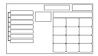
Functional Setup
Select the item you want to check.
|
KG and KE models
KQ model
|
|
Save Users Memory (KQ model)
When replacing the navigation unit, this function allows the dealer to transfer the customer's personal data to the new navigation unit.
This is similar to saving and entering the customer's audio presets when replacing an audio unit. The transferred information includes their Setup settings and personal addresses. The dealer inserts a PC card (like the PC card in the HDS), and then selects the Save Users Memory function. The two functions in this diagnostic screen are Export. Export and Import saves the customer's data to the PC card, and Import moves the PC card files to the new core.
See the FAQs below for information regarding PC cards, and the use of this function.
|
|
|
Export
Select this button to move the customer's data from the original navigation unit to the PC card. Select YES on the Export User Data Confirmation screen. The process takes only a couple of seconds. The system stores two files on the card.
|
|
|
Import
After installing the customer's original DVD in the new navigation control unit, allow the system to boot up. Insert the PC card in the new navigation control unit and enter the navigation diagnostic mode.
Select YES on the Import Confirmation screen.
Import moves the two files stored by the Export process from the PC card to the new navigation unit. When the transfer is finished (a few seconds) the system will automatically reboot. After the system reboots, remove the PC card from the PC slot.
If the Import button is grayed out, follow the troubleshooting in the FAQs below. The customer's files can only be transferred to a new navigation control unit if the Model and the Program Flash shown on the Version screen are the same. These files cannot be transferred from an Accord to a Civic, or from an Accord with version 1.07.00 to a another Accord with version 1.32.00.
|
|
|
Demo Mode (KQ model)
This screen is for factory use only, and should always be set to OFF. Occasionally the DEMO setting is turned ON when vehicles are being used at Auto Shows or similar events. Turning this feature on, allows the navigation system to automatically follow a route to a destination when the vehicle is stationary. The Speed changes the speed of the demo mode.
|
|
|
Mic Level (KG and KE models)
This diagnostic allows you to independently test the microphone and the navigation TALK and BACK buttons. They are used to activate the voice control system. The microphone is located near the map light in the roof console. It is directional, and works only with the voice coming from the drivers seat.
|
|
|
F-CAN System Link
F-CAN (Fast Controller Area Network) passes information between processors on the network. For example, the F-CAN network is used to pass charging system signals between the PCM and the navigation unit for the trip computer cooling fan function. The F-CAN network uses a communication protocol that transmits data at 500 Kbps.
|
|
|
Dealer Setting (KG and KE models)
|
|
|
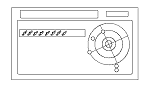
GPS Information
This screen shows the current status of GPS reception. The circular diagram shows the current location of the GPS satellites (yellow numbers) as they would appear in the sky. The outer circle represents the horizon (0 degrees elevation). The middle and inner circles represents 30 and 60 degrees respectively. The very center of the diagram (90 degrees elevation) is directly overhead. Nearby obstructions, like tall buildings will block satellites in that direction. That is why it is necessary to be in an open area to effectively troubleshoot GPS reception issues. The satellite numbers shown on the diagram correspond to the PRN number in the GPS Details screen. There are always at least 24 active GPS satellites in orbit. Because satellites fail, and have to be removed from service, spares are always parked in orbit, ready to be activated. This is why the PRN (satellite ID number) can be greater than 24.
NOTE: To use this screen for troubleshooting, the vehicle should be outside away from buildings, tall trees, and high-tension wires for at least 10 minutes with the engine running.
NOTE: Pressing the map guide button displays the satellite number on each circle.
|
|
|
GPS Detail
By pressing and holding the MENU button for 2 seconds, a GPS Detail screen appears. This screen displays real time incoming satellite positional data when the vehicle is outside in the open. The information shown on this screen is for factory use.
NOTE: The data shown in the GPS Detail screen is an example only.
The table of values shown on the screen has the following columns:
|
|
|
Yaw Rate
This diagnostic checks the yaw rate sensor in the control unit. This device detects when the vehicle turns, and repositions the vehicle position icon on the map screen.
For more detailed information, see the yaw rate sensor theory of operation under System Description.
Example: Vehicle stopped
Example: Vehicle turning
|
|
||||||||||||||||||||||||
|
Yaw Rate Tuning
This diagnostic allows you to graphically display problems with the yaw rate sensor.
Two tests are explained below. For large problems with the sensor values, the stationary test usually confirms whether the sensor is defective. For yaw rate issues related to driving, do the road test described below.
|
|
|
Car Status
Use this screen to confirm that the navigation unit is properly receiving input signals. Signals equal to (0) are OFF, and signals equal to (1) are ON. If the value on the display does not match the actual vehicle status, then check the wire carrying the signal.
The VSP comes from the PCM as a dedicated signal. Internally, the navigation unit compares the actual VP on the map against street data to adjust the pulse to speed scaling factor. As this scaling factor becomes more accurate, the Level gradually increases from 0 to 10 (see the Tire Calibrate diagnostic screen).
The Back signal is used by the navigation unit to allow the map screen to show the VP moving backwards when in reverse. This signal is needed because the Speed Pulse has no direction indication.
The navigation uses the signal to determine whether to put the navigation screen into the Day or Night brightness mode. (Setup screen 1)
ILL CANCEL
This item detects whether the illumination cancel function is in use.
a) OFF (0) if illumination cancel is not selected
b) ON (1) if illumination cancel is activated
The illumination cancel function is activated by increasing the dash brightness to MAX. The F-CAN bus passes this information from the gauge assembly to the navigation control unit.
NOTE: This setting is unaffected by the display mode hard button located below and to the left of the interface dial.
|
|
|
Version
This screen displays the current version information for the navigation system software. In addition, this screen allows the loading of updated software if requested by the factory, or instructed by a Service Bulletin. Software may be loaded from a CD or a PC card.
There are two navigation DVDs produced for this model.
|
|
|
PC Card FAQs
|
|
Error Message Table
|