|
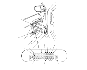
32
|
BLK
|
Under all conditions
|
Check for continuity to ground: There should be continuity.
|
-
Poor ground (G501)
-
An open in the wire
|
|
37
|
BLK
|
Under all conditions
|
Check for continuity to ground: There should be continuity.
|
-
Poor ground (G502)
-
An open in the wire
|
|
14
|
LT GRN
|
Ignition switch ON (II)
|
Measure the voltage to ground: There should be battery voltage.
|
|
|
5
*1
|
BLU
|
Ignition switch ON (II), retractable mirror switch pressed
|
Measure the voltage to ground: There should be battery voltage.
|
|
|
9
|
WHT[PUR]
|
Ignition switch ON (II), power mirror switch in RIGHT [LEFT] mirror position
|
Measure the voltage to ground: There should be battery voltage when the power mirror switch LEFT or DOWN is pressed.
|
|
|
10
|
RED[YEL]
|
Ignition switch ON (II), power mirror switch in RIGHT [LEFT] mirror position
|
Measure the voltage to ground: There should be battery voltage when the power mirror switch RIGHT is pressed.
|
|
|
11
|
GRY[LT BLU]
|
Ignition switch ON (II), power mirror switch in RIGHT [LEFT] mirror position
|
Measure the voltage to ground: There should be battery voltage when the power mirror switch UP is pressed.
|
|
|
1
*2
|
ORN
|
Ignition switch ON (II), connect No. 14 and No. 1 terminals with a jumper wire
|
Check the left [right] power mirror defogger operation: The left [right] power mirror defogger should work (the inside lower edge becomes warm).
|
|
|
7
*1
|
LT BLU
|
Ignition switch ON (II), connect No. 14 and No. 7 [or No. 8] terminals and No. 8 [or No. 7] and No. 32 terminals with jumper wires
|
Check the retract actuator operation: The left [right] mirror should extend (or retract).
NOTE: if the mirror stops moving, disconnect battery power immediately.
|
|
|
8
*1
|
LT GRN
|
|
26
|
PNK
|
Ignition switch ON (II), connect No. 14 and No. 26 terminals with a jumper wire
|
Check the power mirror switch light operation: The power mirror switch light should come on.
|
|