Entry Lights Control System (Driver's and Passenger's MICU, and Door Multiplex Control Unit) Input Test

Driver's MICU
  1. Turn the ignition switch to LOCK (0).
  1. Disconnect driver's under-dash fuse/relay box connectors D, P, Q, and R.
    NOTE: All connector views are wire side of female terminals.
  1. Inspect the connector and socket terminals to be sure they are all making good contact.
    • If the terminals are bent, loose or corroded, repair them as necessary and recheck the system.
    • If the terminals look OK, go to Step 5 .
  1. With the connectors still disconnected, make these input tests at the connectors.
    • If any test indicates a problem, find and correct the cause, then recheck the system.
    • If all the input tests prove OK, go to Step 6 .
    Cavity
    Wire
    Test condition
    Test: Desired result
    Possible cause if desired result is not obtained
    Q1
    BLK
    Under all conditions
    Check for continuity to ground:
    There should be continuity.
    • Poor ground (G502)
    • An open in the wire
    Q2
    BRN
    Under all conditions
    Check for continuity to ground:
    There should be continuity.
    • Poor ground (G501)
    • An open in the wire
    R2
    BRN
    Under all conditions
    Check for continuity to ground:
    There should be continuity.
    • Poor ground (G501)
    • An open in the wire
    R5
    BLK
    Under all conditions
    Check for continuity to ground:
    There should be continuity.
    • Poor ground (G502)
    • An open in the wire
    P4
    PNK
    Under all conditions (Ceiling light switch in middle position and interior light switch * in DOOR position)
    Attach to ground:
    The ceiling light and map light * should come on.
    • Blown No. 16 (7.5 A) fuse in the under-hood fuse/relay box
    • Faulty ceiling light
    • Faulty map light *
    • Faulty interior light switch *
    • Blown bulb
    • An open in the wire
    Q11
    RED
    Under all conditions
    Attach to ground:
    The ignition key light should come on.
    • Blown No. 16 (7.5 A) fuse in the under-hood fuse/relay box
    • Faulty ignition key light
    • An open in the wire

    *:
    With sunroof

  1. Reconnect the connectors to the driver's under-dash fuse/relay box, and make these input tests at the connector.
    • If any test indicates a problem, find and correct the cause, then recheck the system.
    • If all the input tests prove OK, go to Step 7 .
    Cavity
    Wire
    Test condition
    Test: Desired result
    Possible cause if desired result is not obtained
    P9
    WHT
    Under all conditions
    Measure the voltage to ground:
    There should be battery voltage.
    • Blown No. 15 (10 A) fuse in the under-hood fuse/relay box
    • Faulty driver's under-dash fuse/relay box
    • [Faulty passenger's under-dash fuse/relay box]
    • An open in the wire
    D4
    LT GRN
    Left [right] rear door open
    Measure the voltage to ground:
    There should be less than 1 V.
    • Faulty left [right] rear door switch
    • An open in the wire
    Left [right] rear door closed
    Measure the voltage to ground:
    There should be more than 5 V.
    • Faulty left [right] rear door switch
    • A short to ground in the wire
    D12
    BRN [GRN]
    Driver's door open
    Measure the voltage to ground:
    There should be less than 1 V.
    • Faulty driver's door switch
    • An open in the wire
    Driver's door closed
    Measure the voltage to ground:
    There should be more than 5 V.
    • Faulty driver's door switch
    • A short to ground in the wire
    Q18
    WHT
    Ignition key inserted into the ignition switch
    Measure the voltage to ground:
    There should be less than 1 V.
    • Faulty ignition key switch
    • An open in the wire
    Ignition switch in LOCK (0) position, and the ignition key removed from the ignition switch
    Measure the voltage to ground:
    There should be more than 5 V.
    • Faulty ignition key switch
    • A short to ground in the wire

    [ ]:
    RHD model


Passenger's MICU
  1. Disconnect passenger's under-dash fuse/relay box connectors A, E, and H.
    NOTE: All connector views are wire side of female terminals.
  1. Inspect the connector and socket terminals to be sure they are all making good contact.
    • If the terminals are bent, loose or corroded, repair them as necessary and recheck the system.
    • If the terminals look OK, go to Step 10 .
  1. With the connectors still disconnected, make these input tests at the connectors.
    • If any test indicates a problem, find and correct the cause, then recheck the system.
    • If all the input tests prove OK, go to Step 11 .
    Cavity
    Wire
    Test condition
    Test: Desired result
    Possible cause if desired result is not obtained
    A36
    BLK
    Under all conditions
    Check for continuity to ground:
    There should be continuity.
    • Poor ground (G505)
    • An open in the wire
    A37
    BLK
    Under all conditions
    Check for continuity to ground:
    There should be continuity.
    • Poor ground (G505)
    • An open in the wire
    E15
    BLK
    Under all conditions
    Check for continuity to ground:
    There should be continuity.
    • Poor ground (G201) [G302]
    • An open in the wire
    E16
    BLK
    Under all conditions
    Check for continuity to ground:
    There should be continuity.
    • Poor ground (G201) [G302]
    • An open in the wire
    A14
    WHT
    Under all conditions
    Measure the voltage to ground:
    There should be battery voltage.
    • Blown No. 15 (10 A) fuse in the under-hood fuse/relay box
    • An open in the wire
    [E3]
    WHT
    Under all conditions
    Measure the voltage to ground:
    There should be battery voltage.
    • Blown No. 15 (10 A) fuse in the under-hood fuse/relay box
    • An open in the wire
    A35
    BRN
    Ignition switch ON (II)
    Measure the voltage to ground:
    There should be battery voltage.
    • Blown No. 5 (7.5 A) fuse in the driver's under-dash fuse/relay box
    • An open in the wire

    [ ]:
    RHD model

  1. Reconnect the connectors to the passenger's under-dash fuse/relay box, and make these input tests at the connectors.
    • If any test indicates a problem, find and correct the cause, then recheck the system.
    • If all the input tests prove OK, go to Step 12 .
    Cavity
    Wire
    Test condition
    Test: Desired result
    Possible cause if desired result is not obtained
    H25
    LT GRN
    Right [left] rear door open
    Measure the voltage to ground:
    There should be less than 1 V.
    • Faulty right [left] rear door switch
    • An open in the wire
    Right [left] rear door closed
    Measure the voltage to ground:
    There should be 5 V or more.
    • Faulty right [left] rear door switch
    • A short to ground in the wire
    H3
    GRN [BRN]
    Front passenger's door open
    Measure the voltage to ground:
    There should be less than 1 V.
    • Faulty front passenger's door switch
    • An open in the wire
    Front passenger's door closed
    Measure the voltage to ground:
    There should be 5 V or more.
    • Faulty front passenger's door switch
    • A short to ground in the wire

    [ ]:
    RHD model


Door Multiplex Control Unit
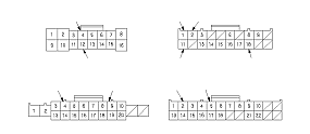
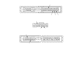
  1. Disconnect the 37P connector from the door multiplex control unit.
  1. Inspect the connector and socket terminals to be sure they are all making good contact.
    • If the terminals are bent, loose or corroded, repair them as necessary and recheck the system.
    • If the terminals look OK, go to Step 15 .
  1. With the connector still disconnected, make these input tests at the connector.
    • If any test indicates a problem, find and correct the cause, then recheck the system.
    • If all the input tests prove OK, go to Step 16 .
    Cavity
    Wire
    Test condition
    Test: Desired result
    Possible cause if desired result is not obtained
    32
    BLK
    Under all conditions
    Check for continuity to ground:
    There should be continuity.
    • Poor ground (G501)
    • An open in the wire
    37
    BLK
    Under all conditions
    Check for continuity to ground:
    There should be continuity.
    • Poor ground (G502)
    • An open in the wire
    13
    WHT
    Under all conditions
    Measure the voltage to ground:
    There should be battery voltage.
    • Blown No. 15 (10 A) fuse in the under-hood fuse/relay box
    • An open in the wire

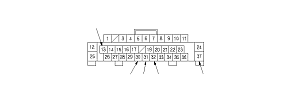
  1. Reconnect the 37P connector to the door multiplex control unit, and make these input tests at the connector.
    • If any test indicates a problem, find and correct the cause, then recheck the system.
    • If all the input tests prove OK, go to Step 17 .
    Cavity
    Wire
    Test condition
    Test: Desired result
    Possible cause if desired result is not obtained
    30
    YEL [GRN]
    Driver's door lock knob switch in LOCK
    Measure the voltage to ground:
    There should be less than 1 V.
    • Poor ground (G501)
    • Faulty driver's door lock knob switch
    • An open in the wire
    Driver's door lock knob switch in neutral or UNLOCK
    Measure the voltage to ground:
    There should be 5 V or more.
    • Faulty driver's door lock knob switch
    • A short to ground in the wire
    31
    WHT
    Driver's door lock knob switch in UNLOCK
    Measure the voltage to ground:
    There should be less than 1 V.
    • Poor ground (G501)
    • Faulty driver's door lock knob switch
    • An open in the wire
    Driver's door lock knob switch in neutral or LOCK
    Measure the voltage to ground:
    There should be 5 V or more.
    • Faulty driver's door lock knob switch
    • A short to ground in the wire

    [ ]:
    RHD model

  1. If multiple failures are found on more than one control unit, replace the driver's under-dash fuse/relay box (includes the driver's MICU). If input failures are related to a particular control unit, replace the control unit.