|
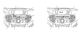
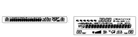
Without Navigation
To check AM or FM reception, press and hold the applicable band button for 5 seconds, then release. The reception level is displayed in decibels (db). You can check the reception with or without the amplifier. Press the A. SEL button to toggle between turning the amplifier on and off. The amplifier is on when the letter A appears next to the db indication. You can change the station with the tuner button to check the reception level of any specific radio station. Compare this value with a known-good vehicle to check the audio unit reception.
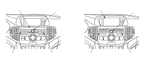
With Navigation
To check FM reception, press and hold the AM/FM button for 5 seconds, the release. To check the AM band, press and hold the AM/FM button for another five seconds, then release. The reception level is displayed in decibels (db). You can check the reception with or without the amplifier. Press the A. SEL button to toggle between turning the amplifier on and off. The amplifier is on when the letter A appears next to the db indication. You can change the station with the tuner button to check the reception level of any specific radio station. Compare this value with a known-good vehicle to check the audio unit reception.
|
 ) is pressed:
 ) is pressed: