|
USB device does not function
NOTE:
-
Some models may not support USB device such as portable digital players.
-
The USB memory used for inspection should conform to the ‘‘USB mass storage class'' standard.
-
Not compatible with USB memory of 128 MB or below.
-
The file format for the music data to be saved to the USB memory for inspection are WMA (Windows Media Audio) and MP3. (Not compatible with MP3 files saved in variable bit rate.)
-
Be sure that the USB device used for inspection functions properly.
-
Turn the ignition switch to ON (II).
-
Operate the AUX button, and check if it changes to USB mode.
|
Does it change to USB mode?
|
-
Connect a properly functioning USB device for inspection.
-
Check that the USB memory for inspection functions properly.
|
YES
|
-
|
Check that there is no dirt or damage in the USB terminal. If there is no abnormality, USB device is either defective or incompatible.■
|
|
NO
|
-
|
|
-
Check if ‘‘NO DATA'' appears when USB device is connected.
-
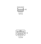
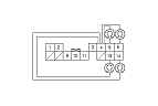
Check the connectors at the USB adapter unit B connector (5P) and USB adapter cable and USB jack.
|
Are the connectors and terminals connected properly?
|
|
YES
|
-
|
|
|
NO
|
-
|
Repair the connection and recheck.■
|
-
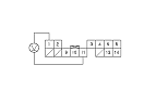
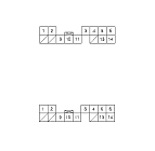
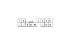
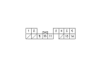
Disconnect USB adapter unit connector B (5P).
-
Check for continuity between USB adapter unit connector B (5P), and USB jack according to the table.
|
|
USB adapter unit connector
|
USB jack
|
|
USB VBUS
|
B1
|
No. 1
|
|
USB DATA−
|
B2
|
No. 2
|
|
USB DATA+
|
B3
|
No. 3
|
|
USB GND
|
B4
|
No. 4
|
|
USB SH
|
B5
|
No. 5
|
|
YES
|
-
|
|
|
NO
|
-
|
Repair open in the wires between the USB adapter unit and USB jack.■
|
-
Check if sound normally comes out from the speakers while selecting radio, CD, etc.
|
YES
|
-
|
|
|
NO
|
-
|
Go to No Sound is heard from the speaker(s):■
|
-
Check if sound is normal when changed to TV.
-
Turn the ignition switch to ON (II).
-
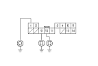
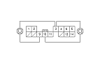
Disconnect USB adapter unit connector A (14P) and the audio unit connector D (14P).
|