|
13
|
WHT
|
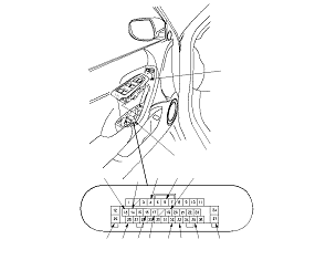
Under all conditions
|
Measure the voltage to ground: There should be battery voltage.
|
|
|
14
|
LT GRN
|
Ignition switch ON (II)
|
Measure the voltage to ground: There should be battery voltage.
|
|
|
25
|
WHT [GRN]
|
Under all conditions
|
Measure the voltage to ground: There should be battery voltage.
|
|
|
32
|
BLK
|
Under all conditions
|
Check for continuity to ground: There should be continuity.
|
-
Poor ground (G501)
-
An open in the wire
|
|
37
|
BLK
|
Under all conditions
|
Check for continuity to ground: There should be continuity.
|
-
Poor ground (G502)
-
An open in the wire
|
|
33
|
BLU
|
Under all conditions(disconnect power seat control unit connector A (40P))
|
Check for continuity between the No. 33 terminal and power seat control unit connector A (40P) No. 39 terminal:There should be continuity.
|
An open in the wire
|
|
35
|
PNK [BLK]
|
Under all conditions(disconnect power seat control unit connector A (40P))
|
Check for continuity between the No. 35 terminal and power seat control unit connector A (40P) No. 40 terminal:There should be continuity.
|
An open in the wire
|
|
4
|
GRN
|
Ignition switch ON (II)
|
Connect the No. 14 and No. 4 terminals:The driving position memory switch indicator 2 should come on.
|
|
|
6
|
PUR
|
Ignition switch ON (II)
|
Connect the No. 14 and No. 6 terminals:The driving position memory switch indicator 1 should come on.
|
|
|
26
|
PNK
|
Ignition switch ON (II)
|
Connect the No. 14 and No. 26 terminals:The driving position memory switch lights should come on.
|
|