SRS Precautions and Procedures
|
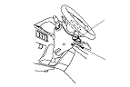
Steering-Related Precautions
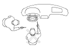
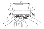
Cable Reel Alignment
|
|
|
|
|
|
|
|
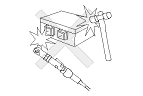
SRS Unit, Front Impact Sensors, and Side Impact Sensors
|
|
|
|
|
Wiring Precautions
Some of the SRS wiring can be identified by special yellow outer covering, and the SRS connectors can be identified by their yellow color. Observe the instructions.
|
|
|
|
|
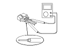
Precautions for Electrical Inspections
|
|
|
|
|
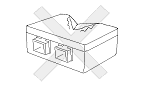
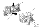
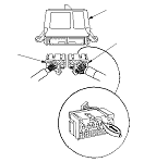
Lever-Locked Connector
The SRS unit connectors have a lever lock.
SRS Unit Connectors
Disconnecting
To release the lock, pull the lever (A) while pushing the lock (B), on the outside of the connector, then pull the connector (C).
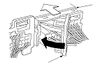
Connecting
|
|
|
To reconnect the connector, push in on the connector sleeve (A). As the connector is pressed in, the lever (B) moves to the locked position.
|
|
|
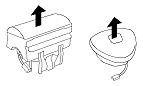
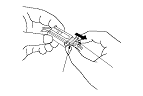
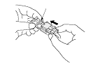
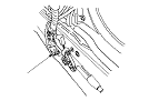
Spring-Loaded Lock Connector
Some SRS system connectors have a spring-loaded lock.
Front Airbag Connectors
Disconnecting
To release the lock, pull the spring-loaded sleeve (A) toward the stop (B) while holding the opposite half of the connector. Then pull the connector halves apart. Be sure to pull on the sleeve and not on the connector.
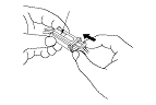
Connecting
|
|
|
To reconnect, hold the pawl-side connector, and press on the back of the sleeve-side connector in the direction shown. As the two connector halves are pressed together, the sleeve (A) is pushed back by the pawl (C). Do not touch the sleeve.
|
|
|
Side Airbag Connector
Disconnecting
To release the lock, pull the spring-loaded sleeve (A) toward the stop (B) while holding the opposite half of the connector. Then pull the connector halves apart. Be sure to pull on the sleeve and not on the connector half.
Connecting
|

|
|
Hold both connector halves, and press them firmly together until the projection (C) of the sleeve-side connector clicks.
|
|
|
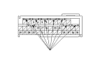
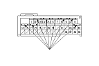
Opening the SRS Unit Shorting Connectors for Diagnosis
Special Tools Required
SRS short canceller
070AZ-SAA0100
NOTE:
When SRS unit connectors A (39P) or B (39P) are disconnected, a short circuit is created in the connector by its own function to prevent an airbag deployment. The circuit may need to be open sometimes when diagnosis is done on the system. Insert the short canceller (No. 070AZ-SAA0100) in the specified cavities when it is necessary to keep the circuit open for diagnosis.
|
|
|
Terminal numbers are shown from the wire side of the female terminals. Insert the short canceller(s) into the cavities on the terminal side of the connector.
|
|
|
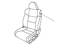
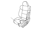
Seats with Side Airbags
Seats with side airbags have a ‘‘SIDE AIRBAG'' label on the seat-back.
|
|
|
Disconnecting System Connectors
Turn the ignition switch to LOCK (0). Disconnect the negative cable from the battery. Wait for 3 minutes before starting the following procedures.
|
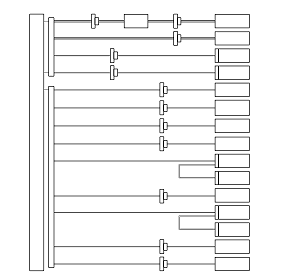
LHD model
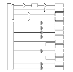
RHD model
|
Driver's Airbag
|
|
|
Front Passenger's Airbag
|
|
|
Side Airbag
|
|
|
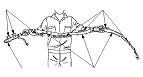
Side Curtain Airbag
|
|
|
Seat Belt Tensioner
|
|
|
Seat Belt Outer Lap Tensioner
|
|
|
SRS Unit
|
|