LKAS Camera Aiming

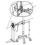
Special Tools Required

Rader aimer set
 070AJ-SDA0100

 or Camera/rader aimer set 070AJ-SDA0300*
*Available by rental from Honda Motor Europe Ltd. for Europe market
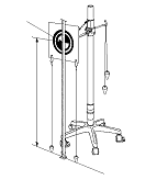
Prepare the items shown
  • HDS
  • Ballpoint pen
  • Tape
  • Camera/rader aimer set 070AJ-SDA0300
NOTE: The LKAS camera must be re-aimed if the LKAS camera unit is removed, replaced or if aiming error occurs. When aiming is not finished, an LKAS indicator and a DTC is stored.
Cautions for the operation environment
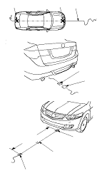
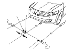
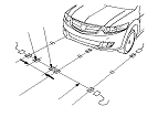
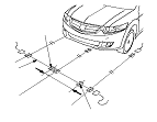
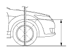
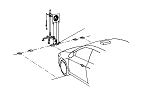
  • LKAS camera aiming should be done on a flat place.
  • Do the aiming in a proper place where you can obtain the about 3 m (9.8 ft.) distance, between a target pattern and the vehicle (from the centre of the front wheel hub).
  • There should be no bright objects at the back of the target (sunlight, windows, illumination, or reflectors) or design similar to the target pattern.
  • Aiming should be done in a well-lighted area.
Set Up the vehicle
  • Aiming the LKAS camera requires the HDS.
  • All wheels of the vehicle should touch the ground.
  • Make sure the suspension has not been modified.
  • Make sure all the tyre sizes are correct and that their pressures are correct.
  • -
    Front/rear tyre: 225/50R17 98V or 235/45R18 98W
    -
    Front/rear tyre pressure: 230 kPa (2.3 kgf/cm 2 , 33 psi)
  • Do not place the wheels of the vehicle on a steel plate or a roller.
  • Make sure the fuel tank is full.
  • Remove the all baggage from the vehicle except the tool kit.
  • Make sure the steering wheel is straight ahead, and do not turn it after setting up the vehicle.
  • Make sure that all doors are closed.
  • Do not put any objects on the instrument panel.
  • Make sure that there are no stains on the lens of the LKAS camera, and the interior and exterior surface of the windshield of the lens parts.
  • Shift the transmission lever to the park or neutral, and apply the parking brake.
  • On same models, if you are towing a trailer, unhitch the trailer.
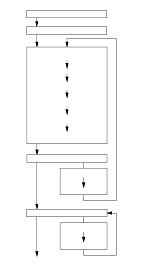
LKAS camera adjustment procedure
There are Static Aiming and Dynamic Aiming procedures, and they need to be done in that order.

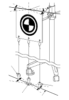
Precaution for the static camera aiming
To complete the aiming, it is necessary to succeed all of three targets (center, passenger's side, driver's side) detections. If the detection for any one of targets failed or aborted on the way, the condition will be the aiming uncompleted.
When the static camera aiming was failure for some reason, aiming failure code is displayed on the HDS. In this case, troubleshoot the indicated failure code with the HDS.
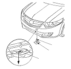
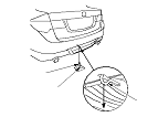
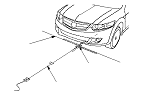
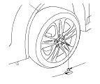
Vehicle Preparation
  1. Turn the ignition switch to ON (II) and make sure only the DTC 10 is indicated with the HDS.
    NOTE: When the LKAS camera is replaced, removed and reattached or fails the aiming process, the DTC 10 is stored and LKAS indicator will be lit. The LKAS camera aiming procedure can be done when this DTC is shown but if any other DTC is indicated do the DTC failure diagnosis. If the cause of the failure cannot be solved then the LKAS camera aiming procedure cannot be done.
  1. Remove the front wheels, and push out the wheel cap (A) on the aluminum wheel from the inside. Reinstall the front wheels.

Special Tools Set-up
  1. Assemble the camera aimer set components (A).
  1. Dangle the three plumb bobs (B) from the target (C). Put the level (D) on the knob of the target. Turn the adjustable hooks (E), and adjust the vertical angle of target pattern surface so that the air bubble in the level is centered.

Settings
Setting the distance between the target and vehicle
NOTE: When marking on the floor, use suitable tape to mark the exact locations.
  1. Hang the plumb bob (A) from the centre line (C) on the jacking pad under the front of the vehicle (line up the plumb bob with the line on the jacking pad), and mark B the spot on the floor where the tip of the plumb bob touches the floor.

  1. Hang the plumb bob (A) from the centre of the rear tow hook (B) on the vehicle centre line and mark C the spot on the floor where the tip of plumb bob touches the floor.

  1. Carefully align the string (A) along point B and point C on the floor. This is the centre line of the vehicle. Tape the string to the floor behind the vehicle aligned with point C. Pull the string forward to a point about 3 m (9.8 ft) in front of the vehicle and tape (D) the string.

  1. Stretch a string (A) perpendicular to the centre line (C) at the point B. Tape both ends of the string on the floor.

  1. Insert the special tool (A) in both driveshaft centre holes.

  1. Hang the plumb bob (A) from the point of the special tool, and mark D1 a spot on the floor where the tip of the plumb bob touches the floor. Repeat this step for the opposite front wheel, and mark D2 a spot on the floor.

  1. Align the string (A) on point D1 and stretch a string perpendicular to the string (B) (this is parallel line of the centre line). Tape the string to the floor behind the aligned with point D1. Repeat this step for the opposite front wheel.

  1. Pull the string (A) forward to a point 3 m (9.8 ft) from point D1. Tape the string mark Y on the floor. Repeat this step for the opposite front wheel, and mark X on the floor.

  1. Stretch a string (A) between point Y and point X, and tape both ends of the string on the floor. Mark the point Z where the string crosses with the centre line (B).

Marking of the central target position
NOTE: When marking on the floor, use suitable tape to mark the exact locations.
  1. On string (A) mark a new point Z1 (central target) which is 52 mm (2.05 in.) from the point Z to the right side.
    NOTE: The LKAS camera is offset to the right side of the vehicle by 52 mm (2.05 in.).

Marking the target position of the right side
NOTE: When marking on the floor, use suitable tape to mark the exact locations.
  1. On string (A) mark a new point Y1 (target of the right side) which is 700 mm (27.56 in.) from the point Z1 to the right side.

Marking the target position of the left side
NOTE: When marking on the floor, use suitable tape to mark the exact locations.
  1. On string (A) mark a new point X1 (target of the left side) which is 700 mm (27.56 in.) from the point Z1 to the left side.

Choose the setting value of the LKAS camera height
  1. Measure the right and left wheel arch height ‘‘H1'' by using the front wheel in either side.
  1. Obtain the front wheel arch height average ‘‘H2'' of the front wheel arch height from the right and left measurement value ‘‘H1'' in either side.
  1. Calculate the difference between the front wheel arch height average value ‘‘H2'' and the front wheel arch height standard value: 691 mm (27.2 in.), and obtain the positive or negative numerical value ‘‘H3'' from the standard value.
  1. Choose the setting value number (the camera height setting value of the HDS) which corresponds to computed numerical value ‘‘H3'' below and it records the number.

    The LKAS camera height setting value of HDS

    Setting value number
    ‘‘H3'' with+ or − numerical value from the standard value (mm)
    (1)
    More than +5 to +15 or less
    (2)
    More than −5 to less than +5
    (3)
    More than −15 to less than −5
    (4)
    More than −25 to less than −15
    (5)
    More than −35 to less than −25

    NOTE: It uses this number when choosing the camera height setting value of HDS in case of the aiming implementation.
    Example
    The front wheel arch height measurement value ‘‘H1'':
    Right front wheel arch height
    687 mm (27.0 in.)
    Left front wheel arch height
    692 mm (27.2 in.)
    The front wheel arch height average value ‘‘H2'':
    689.5 mm (27.1 in.)
    The different from the standard value ‘‘H3'':
    689.5 mm (27.14 in.)−691 mm (27.2 in.) (standard value)= −1.5 mm (−0.06 in.)
    The setting value number which corresponds the numerical value. (2)


    NOTE: When numerical value from the standard value exceeds +15 mm (0.06 in.) or −35 mm, (−1.38 in.) it is not possible do the LKAS camera aiming work. It checks because there is possibility that the frame or suspension has become warped, or the spring has been contracted.

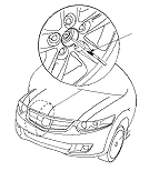
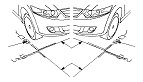
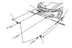
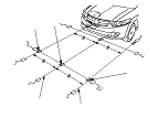
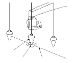
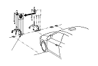
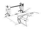
Target pattern surface height adjustment and positioning
  1. Measure the target pattern central point (A) to become the 1,100 mm (43.3 in.) from the floor surface, and adjust the height of the target. Adjust the length of the plumb bobs, should be able to move parallel on the string described in Step 30 .

  1. Position the camera aimer set to the string (A) you made on the floor in the Step 13 , and move the camera aimer set to align the tip of the central plumb bob (B) with a mark Z1.

  1. Turn the target (A) carefully, and adjust the horizontal angle of the target pattern surface by aligning the right and left side plumb bobs (B) on a string (C).
    NOTE: To make the adjustment correctly, align the plumbs so that each of them attached with tip of the plumb bob on a string.

Implementation of the Static Camera Aiming
  1. Connect the HDS to the data link connector (DLC).
  1. Start the engine.
  1. Select LKAS camera aiming from the HDS. At this time, the LKAS indicator (orange) come on and ‘‘CAM'' is displayed at multi-information display (MID).
    NOTE: The static camera aiming status can be confirmed in the MID and LKAS indicator as follows.

The static camera aiming status

STATE
(1)MID
(2)LKAS INDICATOR (ORANGE)
Start the engine
OFF
ON
Starting the static camera aiming
‘‘CAM'' ON
ON
Set the camera height
Starting the target detection
‘‘CAM'' Blink
ON

  1. Set the LKAS camera height to the HDS.
    NOTE: Chooses ‘‘The LKAS camera height setting value number'' which was recorded with the Step 20 .
  1. Check ‘‘central target detection'' from the HDS. ‘‘CAM'' of MID begins a blink when issuing instructions.
    NOTE: It continues to blink until the aiming completes the display of ‘‘CAM'' and it turns off it when the aiming completes. When failing in the aiming, it turned on.

  1. Check ‘‘the central target detection'' was successful on the HDS.

  1. Move the camera aimer set, and make a target pattern central point agree with floor surface position X1 of the left side.
    NOTE: To make the adjustment correctly, align the plumbs so that each of them attached with tip of the plumb bob on a string.
  1. Check ‘‘the left side target detection'' from the HDS.
  1. Check ‘‘the left target detection'' was successful on the HDS.

  1. Move the camera aimer set, and make a target pattern central point agree with floor surface position Y1 of the right side.
    NOTE: To make the adjustment correctly, align the plumbs so that each of them attached with tip of the plumb bob on a string.
  1. Check ‘‘the right side target detection'' from the HDS.
  1. Check ‘‘the right side target detection'' was successful on the HDS.
    NOTE: If the aiming has failed or is aborted, you must start the static camera aiming procedure again.

  1. Make sure ‘‘CAM'' of MID goes out.
    NOTE: The static camera aiming status can be confirmed in the MID and LKAS indicator as follows. If ‘‘CAM'' is displayed on MID the aiming is not finished, then retry the static camera aiming procedure first.

The static camera aiming status

STATE
(1)MID
(2)LKAS INDICATOR (ORANGE)
Aiming is completed
OFF
OFF
Aiming is failure
‘‘CAM'' ON
ON

  1. The static camera aiming was completed. Go to the next step for the dynamic camera aiming procedure.

Precaution for the Dynamic Camera Aiming
Carry out the dynamic camera aiming on a road that has parallel and horizontal lanes that will allow the vehicle to be driven at speeds between 72−112 km/h (45−70 mph) for 10 minutes or more. The aiming will fail unless this is completed within 30 minutes. The dynamic camera aiming may not be successful if it is attempted in bad weather such as rain, fog or snow. The white or yellow lines on the road are not clearly visible due to the reflections caused by a wet road surface. When you do the dynamic camera aiming in the dark, turn the headlights on and ensure that the windscreen and headlights are clean. If the dynamic camera aiming fails for some reason, an aiming failure code is displayed on the HDS. In this case, carry out the troubleshooting for the code indicated using the HDS.
Implementation of the dynamic camera aiming
  1. Turn the ignition switch to LOCK (0).
  1. Check the LKAS camera DTCs with the HDS. Make sure that only DTC 11 indicated.
    NOTE: The LKAS camera aiming procedure can be done when this DTC is shown but if any other DTC is indicated, do the DTC failure diagnosis.
  1. Start the engine. At this time, the LKAS indicator (orange) comes on.
  1. Select dynamic camera aiming from the HDS. ‘‘CAM'' of MID begins a blink when issuing instructions.
  1. Carry out the aiming according to the instruction indicated on the HDS screen. If the dynamic camera aiming fails for any reason an aiming failure cord will be displayed on the HDS. In this case, carry out the troubleshooting for the cords, then retry the aiming procedure first.
    NOTE: The dynamic camera aiming status can be confirmed in the MID and LKAS indicator as follows.

The dynamic camera aiming status

STATE
(1)MID
(2)LKAS INDICATOR (ORANGE)
Start the engine
OFF
ON
Starting the dynamic camera aiming
‘‘CAM'' Blink
ON


  1. Stop the vehicle, after confirming that the aiming has completed. Turn the ignition switch to LOCK (0), then turn it to ON(II) and make sure the LKAS indicator and ‘‘CAM'' of MID does not comes on. If any DTCs are indicated, then carry out the troubleshooting for the codes that are indicated.
    NOTE:
    • Whilst carrying out the aiming procedure, ensure you drive in the centre of the lane and do not use the wiper and turn signal if possible.
    • The dynamic camera aiming status can be confirmed in the MID and LKAS indicator as follows. If ‘‘CAM'' is displayed on MID the aiming is not finished, then retry the dynamic camera aiming procedure first.

The dynamic camera aiming status

STATE
(1)MID
(2)LKAS INDICATOR (ORANGE)
Camera is not detecting the lines of the road with drive the vehicle
‘‘CAM'' Blink
ON
Camera is detected the lines of the road with drive the vehicle
‘‘LKAS'' Blink
ON
Aiming is completed
OFF
OFF
Aiming is failure
‘‘CAM'' ON
ON

  1. Turn the ignition switch to LOCK (0), and disconnect the HDS from the data link connector (DLC).