Millimeter Wave Radar Aiming

Special Tools Required
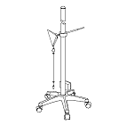
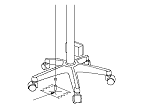
Rader aimer set
 070AJ-SDA0100

 or Camera/rader aimer set 070AJ-SDA0300*
*Available by rental from Honda Motor Europe Ltd. for Europe market
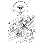
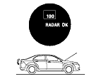
NOTE: The millimeter wave radar must be re-aimed if the unit is removed, replaced or if aiming error occurs. The adaptive cruise control (ACC) indicator comes on if the aiming process is not completed correctly, if there is dust/dirt on the radar unit surface or if an aiming error occurs.
  • Millimeter wave radar aiming incomplete: DTC 107
  • Millimeter wave radar aiming error: DTC 63
  • Millimeter wave radar or emblem surface is contaminated with dust, dirt, ice, or snow: DTC 105
Prepare the items shown
  • HDS
  • Level (commercially available)
  • Tape measure and scale
  • String (about 10 m (32.8 ft) length)
  • String with a plumb bob
  • Ballpoint pen
  • Tape
Set Up the Vehicle
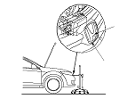
  • Aiming the millimeter wave radar requires the HDS.
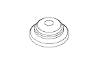
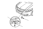
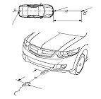
  • Clean the surface of the millimeter wave radar.
  • Make sure the vehicle is not used for towing, and the front of the vehicle height is within spec.
  • Make sure the suspension has not been modified.
  • Make sure all the tyre sizes are correct and that their pressures are correct.
  • Make sure the fuel tank is full.
  • Remove all baggage from the vehicle except the tool kit.
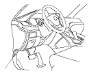
  • Make sure the steering wheel is straight ahead, and do not turn it after setting up the vehicle.
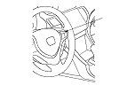
  • Make sure the front grille and the front bumper are installed correctly.
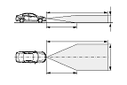
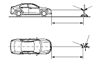
  • Park the vehicle on level ground in a wide open space to avoid misadjustments caused by reflecting objects. The space needs to be 10 m (32.8 ft) in front, 4 m (13.1 ft) in width and 1.2 m (3.9 ft) in height.
  • Shift the transmission lever into park or neutral, and apply the parking brake.
NOTE:
  • When the millimeter wave radar is adjusted on ground that has more than 1 degree of horizontal slope (drainage slope), the vertical aiming cannot be adjusted correctly. Check the levelness of the ground, but it has a continuous slope, and adjust the angle of millimeter wave radar so it is parallel to the ground. Lay a ruler (at least 12'') or other flat straight object on the ground and put the level on top to confirm the levelness of the ground.
  • The vertical aiming can not be set correctly if the vehicle is parked on a slope of more the 1 degree of horizontal slope. Use the level gauge to ensure inspection site is within this parameter.

Vertical Aiming
  1. Put the level (A) on the aiming pad (B) of the millimeter wave radar.
  1. Turn the vertical adjusting bolt (C) with a Phillips screwdriver, and adjust the angle of millimeter wave radar unit so that the air bubble in the level is centered.

Horizontal Aiming
  1. Park the vehicle to an open area with at least this much space in front of it: 10 m (32.8 ft) of distance, 4 m (13.1 ft) wide, and 1.2 m (3.9 ft) height.
  1. Turn the ignition switch to LOCK (0).
  1. Connect the HDS to the data link connector (A).
  1. Turn the ignition switch to ON (II).
  1. NOTE: If DTC 61 or DTC 62 is indicated, troubleshoot the indicated DTC first.
  1. Start the engine.

  1. Turn the main switch (A) to ON.

  1. On the HDS, go to System Selection Menu and select DRIVING SUPPORT. Select ADAPTIVE CRUISE CONTROL. From the Mode Menu, select ADJUSTMENT, then select RADAR AIMING. The MID displays ‘‘4'' for about 2 seconds, and then ‘‘NO TARGET''. If ‘‘NO TARGET'' does not appear on the MID, go to Step 9 . If ‘‘NO TARGET'' does appear on MID, go to Step 11 .

  1. If the radar unit is aimed about straight ahead, and ‘‘NO TARGET'' is not shown on the MID, a temporary DTC will flash in the MID and the screen shown will show on the HDS, indicating the correct amount of open space required. Make sure the correct amount of open space is in front of the vehicle, and move the vehicle as needed, and recheck. If ‘‘NO TARGET'' does appear on the MID, go to Step 11 . In some situations, there may be an object, such as an immovable pole, in the way, or there is an object causing unwanted reflections back to the radar unit. To shield these objects from the radar unit, go to Step 10 .
  1. Stack about six tyres to a height of about 1.7 m (5.6 ft) in front of either the immovable object, such as a pole, or in front of any object causing unwanted reflections. The tyres will block the radar reflections. Make sure ‘‘NO TARGET'' appears on the MID. If it does not appear, move the vehicle to a different location until ‘‘NO TARGET'' appears on the MID.

Setting the Distance Between the Target and the Vehicle
NOTE: When marking on the floor, use suitable tape to mark the exact locations.
  1. Hang the plumb bob (A) from the centre line on the jacking pad (B) under the front of the vehicle (line up the plumb bob with the line on the jacking pad), and mark (C) the spot on the floor where the plumb bob touches the floor.

  1. Hang the plumb bob (A) from the centre of the rear tow hook (B) on the vehicle centre line and mark the spot on the floor (C) where the plumb bob touches the floor.

  1. Tape the string to the floor behind the vehicle aligned with point (B). Pull the string forward to a point 5 m (16.4 ft) in front of the vehicle. Carefully align the string along point (B) and point (A) on the centre line of the vehicle and make a new point (C) 5 m (16.4 ft) in front of the vehicle on the floor.

Special Tools Set-up
  1. Assemble the radar aimer set components.

  1. Adjust the tip (A) of the height rod so that it is aligned with the center of the ‘‘H'' emblem (B).

  1. Position the radar aimer set (A) to the mark (C) you made on the floor in the Step 13 , and point the target (B) at the millimeter wave radar unit.
    NOTE: Hang a plumb bob from the edge of the target assembly and align it with the mark (C) on the floor are aligned.
  1. Put a person or an object equivalent to the driver's weight in the driver's seat.

  1. Follow the onscreen instructions on the HDS to confirm the horizontal aiming is correct or to make the necessary adjustments.
    NOTE: The result of all auto aiming can be confirmed by the HDS, or when ‘‘RADAR OK'' appears on the MID, or by the brake lights illuminating. When the target is not in the range 100±2 or a tone is sounded by the vehicle when the aiming point is out of specification, or when the brake lights do not come on, the auto aiming is not completed correctly. If DTC 120, 121,122, 123, or 124 is indicated, the aiming target is not set correctly. Reset the aiming target.
  1. After adjustment, confirm the MID display and the lighting of the brake lights, and finalize the horizontal aiming (End the aiming process on the HDS).

DTCs (if the aiming is incomplete)
NOTE: If the aiming is incomplete, the MID indicates a DTC. The adaptive cruise control (ACC) unit does not store the DTC, and you can not read the DTCs with the HDS, so note the DTC before cycling the ignition key.

DTC indication (on the MID)
Cause
How to solve
DTC 120
Two or more aiming targets exist.
Remove all reflective objects except the correct special tools, and repeat the aiming procedure.
DTC 121
The width of the aiming target is out of specification.
Use the genuine aiming target, and repeat the aiming procedure.
DTC 122
The distance of the aiming target is out of specification.
Set the distance to the aiming target 4.9−5.1 m (16.0−16.7 ft), and repeat the aiming procedure.
DTC 123
The aiming target is moved.
Do the aiming procedure again.
DTC 124
The right and left position of the aiming target is out of specification.
Reset the aiming target at the correct position, and repeat the aiming procedure.