Steering Gearbox Removal and Installation

Special Tools Required

Ball joint remover, 28 mm
 07MAC-SL00201

Subframe alignment pin
 070AG-SJAA10S

Engine support hanger
 AAR-T1256-J00*

Subhanger stay
 07MAK-PY30100
*: This special tool is available from Snap-on Tools    International, LLC.
Note these items during removal:
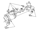
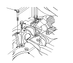
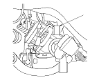
  • Use solvent and a brush, wash any oil and dirt off the end of the steering gearbox. Avoid any electrical parts. Blow dry with compressed air.
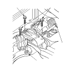
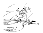
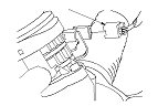
  • Be sure to remove the steering wheel before disconnecting the steering joint, or damage to the cable reel can occur.
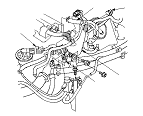
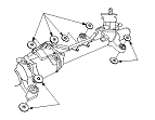
  • Lower the front subframe from the body and remove the steering gearbox through the gap produced by lowering the front subframe.
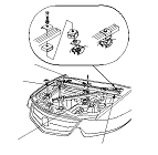
  • The illustrations show LHD model, RHD model is similar for items not shown in this section.
Removal
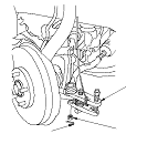
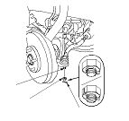
  1. Remove the front wheels.
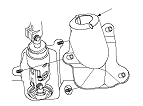
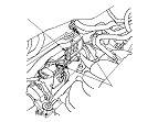
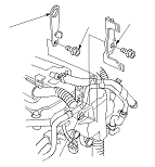
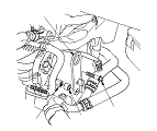
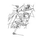
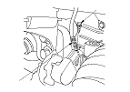
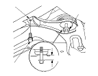
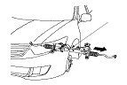
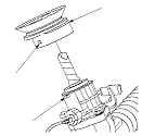
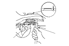
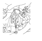
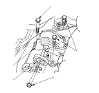
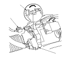
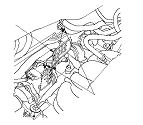
  1. Remove the steering joint cover (A).

  1. Loosen the upper steering joint bolt (A), and remove the lower steering joint bolt (B). Disconnect the steering joint (C) by moving the steering joint toward the column. Do not disconnect the steering joint from the column shaft (D).

  1. Remove the center guide (A) (if equipped) from top of the pinion shaft (B), and discard it. The center guide is for factory assembly use only.
  1. Apply vinyl tape to the splines on the pinion shaft.
  1. Secure the hood in the wide open position with the support rod.

  1. Remove the cotter pin (A) from the tie-rod ball joint, then remove the nut (B).

  1. Remove the P/S heat shield (A).

  1. Disconnect the EPS motor angle sensor 6P connector (A).
  1. Disconnect the EPS motor 3P connector (B) by pushing the lock (C) and pulling down the lever (D). Wrap the connectors with vinyl tape to avoid the contamination from grease or water.

  1. Disconnect the EPS subharness 6P connector (A). Wrap the connectors with vinyl tape to avoid the contamination from grease or water.

  1. Remove the flange bolts (A) and washers (B) from the steering gearbox.
  1. Remove the air cleaner:

  1. R20A3 engine model: Disconnect the EGR valve connector (A), the engine coolant temperature (ECT) sensor 1 connector (B), the EVAP canister purge valve connector (C), and the vacuum tube (D).
  1. R20A3 engine model: Remove the bolts securing the harness cover (E), and remove the harness cover from its bracket.

  1. R20A3 engine model: Remove the harness cover bracket (A), and install the subhanger stay (B) to the cylinder head bolt hole (C) with a 8 x 1.25−16 mm bolt (D).

  1. K23Z3 engine model: Attach the subhanger stay (A) to the water outlet special nut (B) with a spacer (C) and a 10 x 1.25 mm bolt (D).

  1. Install the engine support hanger (AAR-T1256-J00) to the vehicle, and attach the hook (A) to the subhanger stay (B). Tighten the wing nut (C) by hand, and lift and support the engine.

  1. Remove the rear engine mount (A) and dynamic damper (B) (if equipped).
Except K24Z3 engine A/T model
K24Z3 engine A/T model

  1. K24Z3 engine A/T model: Remove the upper base bracket (A) from the base bracket (B).
  1. Raise the vehicle on a lift.
  1. Remove the exhaust pipe A:

  1. Remove the ground cable (A) from the front subframe.

  1. Attach a wood block (A) to the lower center of the front subframe (B). Attach a transmission jack (C) to the center of the wood block and support the front subframe securely by raising the transmission jack.

  1. Remove the transmission lower mount bolts (A).

  1. Remove the front subframe middle mounts (A).

  1. Remove the flange bolts (A) from the front subframe front stiffeners (B).
  1. Loosen the front subframe mounting bolts (C) so they are about 20 mm (0.79 in.) from the mounting surface. Do not loosen the front subframe mounting bolts more than necessary.

  1. Remove the flange bolts (A) and front subframe mounting bolts (B) from the front subframe rear stiffeners (C).

  1. Lower the jack slowly until the front subframe has dropped about 70 mm (2.76 in.).

  1. Carefully move the steering gearbox (A) toward the driver's side until the pinion shaft clears the fenderwell opening on the body.

  1. Remove the steering gearbox (A) through the fenderwell opening on the driver's side.

  1. Remove the pinion shaft grommet (A) from top of the torque sensor (B).

  1. Remove the EPS subharness (A) from the steering gearbox (B).

Installation
  1. Before installing the steering gearbox, make sure that no grease is on the mating surface of the steering gearbox and the front subframe. To prevent the gearbox mounting bolts from loosening after the installation, remove any grease from the bolt holes.
  1. Wrap vinyl tape to the splines on the pinion shaft (A).
  1. Install the EPS subharness (B) to the steering gearbox (C).

  1. Install the pinion shaft grommet (A). Align the square hole (B) in the pinion shaft grommet with the lug portion (C) on the torque sensor. The grommet must not have a gap at the mating surface of the grommet and torque sensor.

  1. Turn the lip (A) of the pinion shaft grommet.
  1. Slide the steering gearbox (B) between the front subframe and body from the driver's side.

  1. Carefully move the steering gearbox (A) toward the passenger's side until the pinion shaft clears the wheel well opening on the body.
  1. Continue moving the steering gearbox toward the passenger's side until the steering gearbox is in position.

  1. Install the front subframe front stiffeners (A) and the front subframe rear stiffeners (B), then loosely install the new front subframe mounting bolts (C), new flange bolts (D), and flange bolts (E).

  1. Align the front subframe using the 15.7 mm end of the subframe alignment pin. Vertically install the subframe alignment pin, and align the right-rear corner of the front subframe and vehicle frame holes, then loosely tighten the subframe mounting bolt (A) unit the front subframe contacts the body frame.
  1. Loosely tighten the left-rear subframe mounting bolt with the same procedure as right-rear using the subframe alignment pin.

  1. Tighten the right-rear subframe mounting bolt (A) to the specified torque with the subframe alignment pin installed.
  1. Tighten the left-rear subframe mounting bolt to the specified torque with the subframe alignment pin installed.

  1. Tighten the subframe mounting bolts (A) to the specified torque.
  1. Tighten the flange bolts (B) to the specified torque.

  1. Tighten the flange bolts (A) to the specified torque.

  1. Install the front subframe middle mounts (A) with new mounting bolts, and tighten them to the specified torque.

  1. Install the transmission lower mount bolts (A), and tighten them to the specified torque.
  1. Remove the transmission jack supporting the front subframe.

  1. Install the ground cable (A) to the front subframe.
  1. Install the exhaust pipe A:
  1. Lower the vehicle.

  1. K24Z3 engine A/T model: Install the upper base bracket (A) to the base bracket (B) with a new mounting bolt (C) and mounting bolts (D), then tighten them to the specified torque.

  1. Install the rear engine mount (A) and dynamic damper (B) (if equipped) with new mounting bolts, and tighten them to the specified torque.
  1. Remove the engine support hanger.
Except K24Z3 engine A/T model
K24Z3 engine A/T model

  1. R20A3 engine model: Remove the subhanger stay (A) and bolt (B), and install the harness cover bracket (C) on the engine.

  1. K24Z3 engine model: Remove the subhanger stay (A) from the water outlet special nut (B).

  1. R20A3 engine model: Install the harness cover (A) on its bracket, and secure it with the bolts.
  1. R20A3 engine model: Reconnect the engine coolant temperature (ECT) sensor 1 connector (B), the EGR valve connector (C), the EVAP canister purge valve connector (D), and vacuum tube (E), and secure the tube with the clip.

  1. Install the washers (A) and flange bolts to the steering gearbox, then loosely tighten the flange bolts.
    NOTE: Make sure that the washers is in position correctly.
  1. Tighten the front/driver's side of the flange bolt (B) to the specified torque.
  1. Tighten the front/passenger's side of the flange bolt (C) to the specified torque.
  1. Tighten the rear side of the flange bolt (D) to the specified torque.

  1. Connect the EPS subharness 6P connector (A).

  1. Remove the vinyl tape, then connect the torque sensor 6P connector (A) to the steering gearbox.
  1. Pull up the lever (B) of the EPS motor 3P connector (C), then confirm the connector is fully seated.

  1. Install the P/S heat shield (A) with the flange bolts, and tighten them to the specified torque.
  1. Install the air cleaner:

  1. Wipe off any grease contamination from the ball joint tapered section and thread. Reconnect the tie-rod ball joint (A) to the knuckle. Install the nut (B), and tighten it to the specified torque.
  1. Install a new cotter pin (C) and bend it as shown.
  1. Install the front wheels, then set the wheels in the straight ahead position.
    NOTE: Before installing the wheel, clean the mating surfaces of the brake disc and the inside of the wheel.
  1. Center the steering rack within its stroke.

  1. Slip the lower end of the steering joint (A) onto the pinion shaft (B) taking care to align the gap (C) within the angle.
    NOTE: Pick up the tabs (D) of the pinion shaft grommet, and turn up the lip of the pinion shaft grommet securely in place. Make sure that light does not enter from the space between the pinion shaft grommet and the body.

  1. Align the bolt hole (A) on the steering joint with the groove (B) around the pinion shaft, then loosely install the lower steering joint bolt (C). Be sure that the joint bolt is securely in the groove in the pinion shaft.
  1. Pull on the steering joint to make sure that the steering joint is fully seated, then tighten the lower joint bolt to the specified torque.
  1. Tighten the upper steering joint bolt (D) to the specified torque.

  1. Install the steering joint cover (A).
  1. With the tyres raised off the ground, check for the following symptoms by turning the steering wheel fully to the right and left several times.
    Symptom
    Probable cause
    Rubbing sound coming from the lower steering column area.
    Steering column joint is contacting the cover.
    Grating sound from the lower steering column area, or a rough feeling during steering.
    Poor engagement of the pinion shaft serrations.
    Noise from around the steering wheel during steering.
    Poor engagement of the SRS cable reel with the steering wheel, or a damaged cable reel.

    • Turn the ignition switch to ON (II) and check that the SRS indicator should came on for about 6 seconds and then go off.
    • Make sure the horn and turn signal switches work properly.
    • Make sure the steering wheel switches work properly.
  1. After installation, do these checks: