Driveshaft Reassembly
|
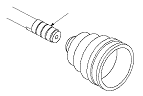
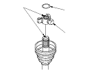
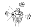
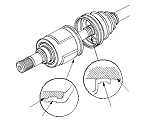
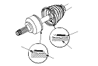
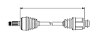
Exploded View
Special Tools Required
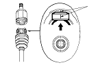
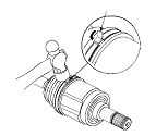
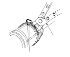
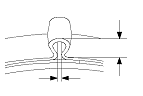
Boot band tool,
KD-3191
or equivalent, commercially available Boot band pliers,
Kent-Moore J-35910
or equivalent, commercially available
Boot band pliers, commercially available
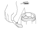
NOTE: Refer to the Exploded View, as needed, during this procedure.
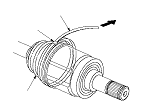
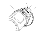
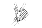
Inboard Joint Side
|
|
|
|
|
|
|
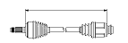
Left driveshaft

Right driveshaft
|
||||||||||||||||||||||||||
|
|
|
|
|
|
|
|
|
|
|
|
|
|
|
|
|
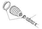
Outboard Joint Side
|
|
|
|
|
|
|
|
|
|
|
|
|
|
||||||||||||||||||||
|
|
|
Left driveshaft
Right driveshaft
|
||||||||||||||||||||||||||
|
|
|
|