Front Knuckle Ball Joint Replacement

Special Tools Required

C-frame
 070AF-S5A0310

Air hammer attachment
 070AF-TA00310

Attachment, 53 x 50 mm
 070AF-TA00320

Ball joint base attachment, 62 x 50 mm DP77
 070AF-TA00330

Ball joint remover, 28 mm
 07MAC-SL00201
NOTE:
  • When use the air hammer, confirms that the tank of the air compressor filled with air and gauge of the tank shows more than 440 kPa (4.5 kgf/cm 2 , 64 psi).
  • Replace the knuckle as an assembly if the knuckle ball joint has the paint mark (A). Paint mark indicate the ball joint has been replaced.

  1. Remove the front wheel.
  1. Remove the wheel speed sensor harness bracket (A) and the wheel speed sensor (B) from the knuckle. Do not disconnect the wheel speed sensor connector.

  1. Raise the stake (A), then remove the spindle nut (B).

  1. Remove the cotter pin (A) from the tie-rod end ball joint, then remove the nut (B).
    NOTE: During installation, install the new cotter pin after tightening the nut, and bend its end as shown.

  1. Remove the dumper fork mounting nut (A) while holding the mounting bolt (B), then remove the mounting bolt.
    NOTE: Use the new dumper fork mounting bolt and the new mounting nut, and torque the nut while holding the bolt during reassembly.

  1. Remove the cotter pin (A) from the knuckle ball joint, then remove the castle nut (B).
    NOTE: During installation, insert the new cotter pin into the ball joint pin hole from the front to the rear of the vehicle, and bend its end as shown. Check the ball joint pin hole direction before connecting the ball joint.
  1. NOTE:
    • Be careful not to damage the ball joint boot when installing the remover.
    • Do not force or hammer on the lower arm, or pry between the lower arm and the knuckle. You could damage the ball joint.

  1. Remove the driveshaft outboard joint (A) from the knuckle (B) by tapping the driveshaft end (C) with a soft face hammer while drawing the hub outward, then disconnect the knuckle/hub.
    NOTE:

  1. Remove the front knuckle ring (A) from the knuckle.
  1. Remove the boot clip (B) and the boot (C), then wipe grease off the exposed portion of the ball joint.

  1. Install the air hammer attachment on the commercially air hammer (A) for removing the ball joint.
    NOTE: Make sure the attachment is installed surely to the air hammer.

  1. Remove the ball joint (A) from the knuckle (B) by pushing the ball joint upward with the ball joint attachment and the air hammer (C).
    NOTE:
    • When removing the ball joint, use the air hammer according to the equipment manufacturer's instructions.
    • When removing the ball joint, adjust the clearance between the ball joint housing and the attachment to remove the ball joint easily.

  1. Position the attachment over the new ball joint (A) and position the ball joint base attachment under the knuckle (B), then install the C-frame.
  1. Tighten the pressure bolt (C) of the C-frame until the ball joint shoulder is fully seated in the knuckle.

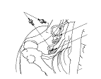
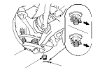
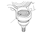
  1. Using a yellow oil-based paint marker, paint a mark (A) to top of the knuckle ball joint as shown.
    NOTE: The paint mark is used to identify a knuckle that has had the ball joint replaced. Do not replace the ball joint with the paint mark; you must replace the knuckle.
  1. Install all of the removed parts in the reverse order of removal, and note these items:
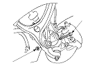
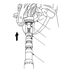
    • First install all the components, and lightly tighten the bolts and the nuts, then raise the suspension to load it with the vehicle's weight before fully tightening it to the specified torque values. Do not place the jack against the ball joint pin of the knuckle.
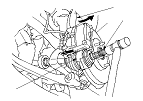
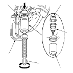
    • Be careful not to damage the ball joint boot when connecting the knuckle.
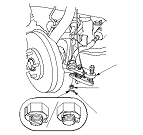
    • Before connecting the ball joint, degrease the threaded section and the tapered portion of the ball joint pin, and the ball joint connecting hole, and the threaded section and the mating surfaces of the castle nut.
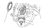
    • Torque the castle nut to the lower torque specification, then tighten it only far enough to align the slot with the ball joint pin hole. Do not align the castle nut by loosening it.
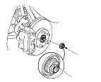
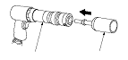
    • Use a new spindle nut on reassembly.
    • Before installing the spindle nut, apply a small amount of engine oil to the seating surface of the nut. After tightening, use a drift to stake the spindle nut shoulder against the driveshaft.
    • Before installing the wheel, clean the mating surfaces of the brake disc and the inside of the wheel.