Wheel Alignment

Special Tools Required

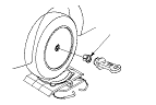
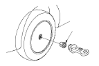
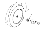
Wheel alignment gauge attachment, 64 x 40 mm
07MGK-0010100
The suspension can be adjusted for front and rear toe.
Pre-Alignment Checks
For proper inspection and adjustment of the wheel alignment, do these checks:
  1. Release the parking brake to avoid an incorrect measurement.
  1. Make sure the suspension is not modified.
  1. Make sure the fuel tank is full, and that the spare tyre or the temporary repair kit, the jack, and the tools are in place on the vehicle.
  1. Check the tyre size and tyre pressure according to tyre information.
  1. Check the suspension ball joints.
  1. Before doing alignment inspections, be sure to remove all extra weight from the vehicle, and no one should be inside the vehicle (driver or passengers).
  1. Bounce the vehicle up and down several times to stabilize the suspension.
  1. Check that the steering column is set at the center tilt and telescopic position.

Front Caster Inspection
  1. Raise the front of the vehicle, and remove the wheel caps.
    NOTE: Push out the cap on the aluminum wheel from the inside after removing the wheel.
  1. Set the turning radius gauges beneath the front wheels, and place the boards under the rear wheels the same thickness as the turning radius gauges, then lower the vehicle.
    NOTE: Be sure that the vehicle is level with the wheels on the turning radius gauges and the boards.
  1. Install the wheel alignment gauge attachment (A) and camber/caster gauge on the wheel hub, and apply the front brake.
  1. Turn the front wheel 20 ° outward, then turn the adjusting screw of the camber/caster gauge to set the bubble at 0 °.
  1. Turn the wheel 20 ° inward and read the caster angle on the gauge with the bubble at the center of the gauge.
    Front caster angle:
    With 16 inch wheels: 3 ° 43 ' +10 ' −50 '
    With 17 inch wheels: 3 ° 47 ' +10 ' −50 '
    With 18 inch wheels: 3 ° 52 ' +10 ' −50 '
    (Maximum difference between the right and left side: 0 ° 30 ')

    • If the measurement is within specifications, measure the front camber angle.
    • If the measurement is not within specifications, check for bent or damaged suspension components.

Front Camber Inspection
  1. Turn the front wheels to the straight ahead position.
  1. Raise the front of the vehicle, and remove the wheel caps.
    NOTE: Push out the cap on the aluminum wheel from the inside after removing the wheel.
  1. Install the wheel alignment gauge attachment (A) and camber/caster gauge on the wheel hub.
  1. Read the camber angle on the gauge with the bubble at the center of the gauge.
    Front camber angle:
    With 16 inch wheels: 0 ° 02 '±30 '
    With 17 inch wheels: 0 ° 00 '±30 '
    With 18 inch wheels: 0 ° 03 '±30 '
    (Maximum difference between the right and left side: 0 ° 30 ')

    • If the measurement is within specifications, measure the rear camber.
    • If the measurement is not within specifications, check for bent or damaged suspension components.

Rear Camber Inspection
  1. Raise the rear of the vehicle, and remove the wheel caps.
    NOTE: Push out the cap on the aluminum wheel from the inside after removing the wheel.
  1. Install the wheel alignment gauge attachment (A) and camber/caster gauge on the wheel hub.
  1. Read the camber angle on the gauge with the bubble at the center of the gauge.
    Rear camber angle:
    With 16 inch wheels: −0 ° 50 '±30 '
    With 17 inch wheels: −1 ° 00 '±30 '
    With 18 inch wheels: −1 ° 12 '±30 '
    (Maximum difference between the right and left side: 0 ° 30 ')

    • If the measurement is within specifications, measure the toe-in.
    • If the measurement is not within specifications, check for bent or damaged suspension components.

Front Toe Inspection/Adjustment
  1. Set the steering column to the middle tilt and telescopic positions. Center the steering wheel spokes, and hold it.
  1. Check the toe with the wheels pointed straight ahead.
    Front toe-in:
    0±2 mm (0±0.08 in.)

    • If adjustment is required, go to Step 3 .
    • If no adjustment is required, go to rear toe inspection/adjustment.
  1. Loosen the tie-rod locknuts (A) while holding the flat surface sections (B) of the tie-rod end with a wrench, and turn both tie-rods (C) until the front toe is within specifications.
  1. After adjusting, tighten the tie-rod locknuts to the specified torque valve. Reposition the rack end boot if it is twisted or displaced.
  1. Go to rear toe inspection/adjustment.
    NOTE: Adjust both the right and left wheels at the same time by the same amount in opposite directions to obtain the correct toe and to keep the steering wheel straight.

Rear Toe Inspection/Adjustment
  1. Release the parking brake to avoid and incorrect measurement.
  1. Check the toe.
    Rear toe-in:
    2±2 mm (0.08±0.08 in.)

    • If adjustment is required, go to Step 3 .
    • If no adjustment is required, measure the turning angle.
  1. Hold the adjusting bolt (A) on the rear control arm (B), and loosen the self-locking nut (C).
  1. Replace the self-locking nut with a new one, and lightly tighten it.
    NOTE: Always use a new self-locking nut whenever it has been tightened to the specified torque.
  1. Adjust the rear toe by turning the adjusting bolt until the toe is correct.
  1. Tighten the self-locking nut while holding the adjusting bolt to the specified torque valve.

Turning Angle Inspection
  1. Raise the vehicle and set the turning radius gauges beneath the front wheels, and place the boards under the rear wheels the same thickness as the turning radius gauges, then lower the vehicle.
    NOTE: Be sure that the vehicle is level with the wheels on the turning radius gauges and the boards.
  1. Turn the wheel right and left while applying the brake, and measure the turning angle of both wheels.
    Turning angle:
    With 16 inch wheels:
    Inward: 39 ° 04 '±2 °
    Outward (reference): 31 ° 33 '
    With 17 inch wheels:
    Inward: 38 ° 58 '±2 °
    Outward (reference): 31 ° 28 '
    With 18 inch wheels:
    Inward: 36 ° 59 '±2 °
    Outward (reference): 30 ° 23 '

  1. If the measurement is not within the specifications, even up both sides of the tie-rod threaded section length while adjusting the front toe. If it is correct, but the turning angle is not within the specifications, check for bent or damaged suspension components.